Page 511 - Air and Gas Drilling Manual
P. 511
10-36    Air and Gas Drilling Manual
                               As can be seen in the above, the right and left hand sides of Equation 6-88 yield the
                               same answer.  This shows that the upper limit pressure is correct.
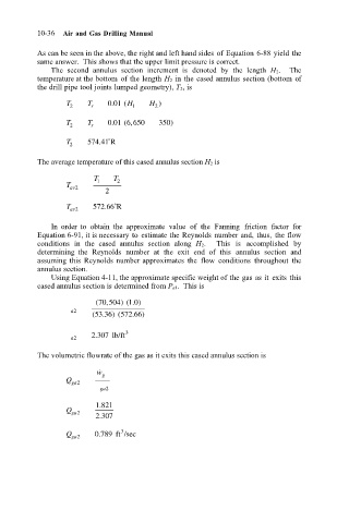
                                   The  second  annulus  section  increment  is  denoted  by  the  length  H 2.    The
                               temperature at the bottom  of the length H 2 in  the cased annulus section (bottom of
                               the drill pipe tool joints lumped geometry), T 2, is
                                      T 2  T r  001 ( H 1  H )
                                                 .
                                                           2
                                                 .
                                      T    T    0 01 6 650  350)
                                                     ,
                                                    (
                                       2    r
                                      T 2  574 41˚R
                                              .
                               The average temperature of this cased annulus section H 2 is
                                             T 1  T 2
                                      T
                                       av2
                                               2
                                               .
                                      T av2  572 66˚R
                                   In  order  to  obtain  the  approximate  value  of  the  Fanning  friction  factor  for
                               Equation 6-91, it is necessary to  estimate the Reynolds number and, thus,  the flow
                               conditions  in  the  cased  annulus  section  along  H 2.    This  is  accomplished  by
                               determining  the  Reynolds  number  at  the  exit  end  of  this  annulus  section  and
                               assuming this  Reynolds number approximates  the  flow  conditions  throughout  the
                               annulus section.
                                   Using Equation 4-11, the approximate specific weight of the gas as it  exits this
                               cased annulus section is determined from P a1.  This is
                                                      .
                                               ,
                                             ( 70 504) ( 1 0)
                                       a2
                                               .
                                            ( 53 36) ( 572 66)
                                                      .
                                             .
                                            2 307 lb/ft 3
                                       a2
                               The volumetric flowrate of the gas as it exits this cased annulus section is
                                             w ˙ g
                                      Q ga2
                                              ga2

                                             1 821
                                              .
                                      Q ga2
                                              .
                                             2 307
                                                   3
                                              .
                                      Q ga2  0 789 ft /sec

