
Page 354 - Applied Process Design For Chemical And Petrochemical Plants Volume III
P. 354
66131_Ludwig_CH11A 5/30/2001 4:49 PM Page 311
Refrigeration Systems 311
(1)
(2) Figure 11-22. Basic features of mechanical refrigeration cycle.
eral standardized designs fit each refrigerant, and this
affords some economy in purchasing units developed for
the application. Drivers for centrifugal compressors are usu-
ally steam turbine or electric motor through gears, and for
reciprocating compressors, the electric motor through
gears or belts is frequently used; see Reference 31.
Condensers
Condensers are usually designed to use water as the
coolant for condensing the refrigerant. In some cascade or
very low-temperature systems, one refrigerant may be used
to condense a second refrigerant. The units are designed
with good heat transfer principles. To improve heat transfer
area characteristics of the tubes, finned tubes are helpful for
the chloro-fluoro-refrigerants.
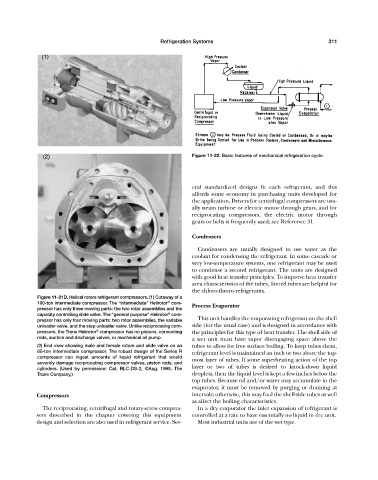
Figure 11-21D. Helical rotors refrigerant compressors. (1) Cutaway of a
®
100-ton intermediate compressor. The “intermediate” Helirotor com- Process Evaporator
pressor has only three moving parts: the two rotor assemblies and the
®
capacity controlling slide valve. The “general purpose” Helirotor com-
pressor has only four moving parts: two rotor assemblies, the variable This unit handles the evaporating refrigerant on the shell
unloader valve, and the step unloader valve. Unlike reciprocating com- side (for the usual case) and is designed in accordance with
pressors, the Trane Helirotor compressor has no pistons, connecting the principles for this type of heat transfer. The shell side of
®
rods, suction and discharge valves, or mechanical oil pump. a wet unit must have vapor disengaging space above the
(2) End view showing male and female rotors and slide valve on an tubes to allow for free surface boiling. To keep tubes clean,
85-ton intermediate compressor. The robust design of the Series R refrigerant level is maintained an inch or two above the top-
compressor can ingest amounts of liquid refrigerant that would most layer of tubes. If some superheating action of the top
severely damage reciprocating compressor valves, piston rods, and
cylinders. (Used by permission: Cat. RLC-DS-2, ©Aug. 1995. The layer or two of tubes is desired to knock-down liquid
Trane Company.) droplets, then the liquid level is kept a few inches below the
top tubes. Because oil and/or water may accumulate in the
evaporator, it must be removed by purging or draining at
Compressors intervals; otherwise, this may foul the shell-side tubes as well
as affect the boiling characteristics.
The reciprocating, centrifugal and rotary-screw compres- In a dry evaporator the inlet expansion of refrigerant is
sors described in the chapter covering this equipment controlled at a rate to have essentially no liquid in the unit.
design and selection are also used in refrigerant service. Sev- Most industrial units are of the wet type.