Page 683 - Automotive Engineering Powertrain Chassis System and Vehicle Body
P. 683
CHAP TER 2 1. 1 Interior noise: Assessment and control
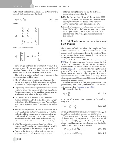
under operational conditions. This is the matrix inversion obtained from (4) multiplied by the body side
method (full matrix method), that is: accelerations measured in (3).
7. Use the forces obtained from (6) along with the NTF
½F¼½A 1 ½€ x (21.1.20) from (5) to estimate the partial sound pressure in the
passenger compartment due solely to vibration
where power transmitted across each engine mount.
2 3 8. Sum all of the partial sound pressure contributions
€ x 11 € x 12 € x 1n from all of the identified noise paths on a polar plot
6 / 7
6 F 1 F 2 F n 7 (or Nyquist diagram) and compare the result with
6 7
6 € x 21 € x 22 7 the measured total sound pressure for validation of
6
½ A¼ 6 F 1 F 2 / / 7 the method.
7
6 7
6 « « « « 7
6 7
4 € x € x 5
m1 mn 21.1.2.4 Non-invasive methods for noise
/ /
F 1 F n path analysis
is the accelerance matrix The practical difficulty with both the complex stiffness
and the matrix inversion method is that the source must
2 3 2 3
€ x at some point be disconnected from the receiver. There
1 F 1
6 € x 7 6 F 7 are at least two further methods in the literature that do
½€ x¼ 6 2 7 and ½F¼ 6 2 7 not require this disconnection.
5
5
4
4
«
«
€ x m F n The first, the TopExpress MPSD system (Harper et al.,
1993) simplifies the equations of motion by assuming that
the various transmission paths can only interact via their
For a unique solution, the number of measured re- attachments to the source and/or the structure as illus-
sponses m must be at least equal to the number of trated in Fig. 21.1-4. The simplified matrix equation takes
identified forces n. If m > n then the equation is over- account of forces exerted on the paths by the source and
determined and a least square estimate is found. forces exerted on the source by the paths. The matrix
The matrix inversion method may be applied to the equation may be solved for the forces at the support ends
engine mounting problem thus: of the structure, and the measured NTF may then be used
1. Identify all probable vibration paths between the to calculate radiated sound.
source (the engine) and the receiver (a microphone Another non-invasive technique originates from TNO
positioned in the passenger compartment). (Netherlands) and ISVR (Southampton) – the equiva-
2. Organise a phase reference signal for use in subsequent lent forces method (Janssens et al., 1999).
measurements. This might be an electrical signal taken Here, transfer functions
from the tachometer or the amplified output from an a i
accelerometer attached to the engine block. A ij ¼ F j (21.1.21)
3. On the test track, or the rolling dynamometer,
measure acceleration levels in the three axes (x, y, z) are measured at convenient positions on the machine
on the body side of the engine mounts. Analyse these along with NTF
levels either as power spectral densities or as ‘order- P k a j
levels’. H kj ¼ ¼ (21.1.22)
F j Q R
4. Remove the engine from the vehicle and measure the
input accelerances in the three axes (x, y, z) on the where P k is the acoustic pressure, F j is the force and Q R is
body side of the mounts due to force excitation ap- the volume acceleration and a j is the acceleration.
plied in each of the three axes in turn. The force The inventive part of the method is an analytical step
excitation is applied with either a shaker or using of determining the amplitude and phase of a set of
a hammer fitted with a force transducer at its tip. equivalent forces fF j g EQ which when applied at the po-
sitions j would reconstruct the vibration field due to the
5. With the engine still removed from the vehicle,
measure the NTF using the force excitation from (4) machine fa i g mach as closely as possible
and a microphone in the passenger compartment. 1
F j ¼ A ij fa i g (21.1.23)
EQ mach
6. Estimate the forces applied at each engine mount
k path
from the inverse of the full accelerance matrix fP g ¼½H F j EQ (21.1.24)
kj
694

