
Page 570 - Subyek Computer Aided Design - [David Planchard] Engineering Design with SOLIDWORKS
P. 570
Top-Down and Sheet Metal Parts Engineering Design with SOLIDWORKS® 2018
• Insert Sheet Metal assembly features.
• Replace Components in an assembly.
• Insert a Design Table.
• Create a sheet metal part by starting with a solid part and inserting a Shell feature,
Rip feature, and Sheet Metal Bends feature.
• Create a Sheet Metal part by starting with a Base Flange feature.
• Use the following SOLIDWORKS features: Extruded Boss/Base, Extruded Cut,
Shell, Hole Wizard, Linear Pattern, Sketch Driven Pattern, Pattern Driven Component
Pattern, Rip, Insert Bends, Flatten, Hem, Edge Flange, Jog, Flat Pattern, Break
Comer/Comer Trim, Miter Flange, Base Flange/Tab, Unfold/Fold, Mirror
Components and Replace Component.
Project Situation
You now work for a different company. Life is full with opportunities. You are part of a
global project design team that is required to create a family of electrical boxes for
general industrial use. You are the project manager.
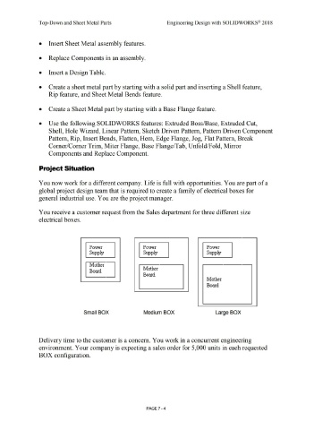
You receive a customer request from the Sales department for three different size
electrical boxes.
Power Power Power
Supply Supply Supply
l\'1:other
Mother
Board
Board
Mother
Board
Small BOX Medium BOX Large BOX
Delivery time to the customer is a concern. You work in a concurrent engineering
environment. Your company is expecting a sales order for 5,000 units in each requested
BOX configuration.
PAGE 7 - 4