
Page 571 - Subyek Computer Aided Design - [David Planchard] Engineering Design with SOLIDWORKS
P. 571
Engineering Design with SOLIDWORKS® 2018 Top-Down and Sheet Metal Parts
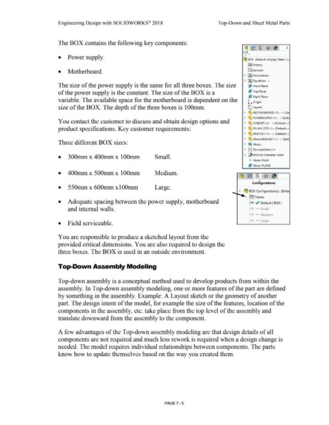
The BOX contains the following key components:
~ I r~~r: ~·1 $"1 ~ I >
\{·
• Power supply.
~ BOX (Default <Display State-1 > J
~ I History
• Motherboard. [0:J Sensors
• (A] Annotations
• ~ Equations ->
The size of the power supply is the same for all three boxes. The size ~ Front Plane
of the power supply is the constant. The size of the BOX is a i:P Top Plane
1::12 Right Plane
variable. The available space for the motherboard is dependent on the L Origin
size of the BOX. The depth of the three boxes is 1 OOmm. C.. Layout
• ~ MOTHERBOARD<1 > - >(De·
• ~ POWERSUPPLY<1> · > (Defa
You contact the customer to discuss and obtain design options and • ~ CABINET <2> -> (Default< <I
product specifications. Key customer requirements: • ~ FH-M4-25Zl<1> (Default<<
• ~ BRACKET< 1 > -> (Default<<
• ~ MirrorBRACKET <1 > -> (Def,
Three different BOX sizes: • ®@ Mates
• ~g DerivedLPattern1
• 300mm x 400mm x lOOmm Small. • ~ 05.0 (5) Diameter Hole1
1t Mirror Point
ij Mirror PLANE
•
• 400mm x 500mm x 1 OOmm Medium.
• 550mm x 600mm xlOOmm Large.
.... ~ BOX Configuration(s) (Defa1
-+-......
• fi~] Tables
• Adequate spacing between the power supply, motherboard ~x ~ Default [ BOX J
and internal walls. 1 x Small
x Medium
x Large
• Field serviceable.
You are responsible to produce a sketched layout from the
provided critical dimensions. You are also required to design the
three boxes. The BOX is used in an outside environment.
Top-Down Assembly Modeling
Top-down assembly is a conceptual method used to develop products from within the
assembly. In Top-down assembly modeling, one or more features of the part are defined
by something in the assembly. Example: A Layout sketch or the geometry of another
part. The design intent of the model, for example the size of the features, location of the
components in the assembly, etc. take place from the top level of the assembly and
translate downward from the assembly to the component.
A few advantages of the Top-down assembly modeling are that design details of all
components are not required and much less rework is required when a design change is
needed. The model requires individual relationships between components. The parts
know how to update themselves based on the way you created them.
PAGE? - 5