
Page 572 - Subyek Computer Aided Design - [David Planchard] Engineering Design with SOLIDWORKS
P. 572
Top-Down and Sheet Metal Parts Engineering Design with SOLIDWORKS® 2018
Designers usually use Top-down assembly modeling to lay their assemblies out and to
capture key design aspects of custom parts specific in the assemblies. There are three key
methods to use for the Top-down assembly modeling approach:
• Individual features method. The Individual features method provides the ability to
reference the various components and sub-components in an existing assembly.
Example: Creating a structural brace in a box by using the Extruded Boss/Base
feature tool. You might use the Up to Surface option for the End Condition and select
the bottom of the box, which is a different part. The Individual features method
maintains the correct support brace length, even if you modify the box in the future.
The length of the structural brace is defined in the assembly. The length is not defined
by a static dimension in the part. The Individual features method is useful for parts
that are typically static but have various features which interface with other assembly
components in the model.
• Entire assembly method. The Entire assembly method provides the ability to create an
assembly from a layout sketch. The layout sketch defines the component locations,
key dimensions, etc. A major advantage of designing an assembly using a layout
sketch is that if you modify the layout sketch, the assembly and its related parts are
automatically updated. The entire assembly method is useful when you create
changes quickly, and in a single location.
, 1 /
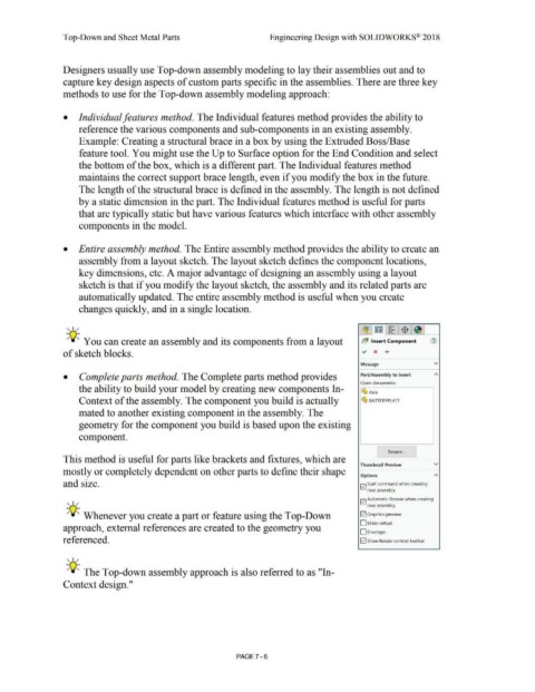
-;Q~ You can create an assembly and its components from a layout b~ Insert Component (1)
of sketch blocks. ~ x ....
Message v
• Complete parts method. The Complete parts method provides Part/Assembly to Insert
Open documents:
the ability to build your model by creating new components In-
~ Axle
Context of the assembly. The component you build is actually ~ BAITERYPLATE
mated to another existing component in the assembly. The
geometry for the component you build is based upon the existing
component.
I Browse... J
This method is useful for parts like brackets and fixtures, which are
Thumbnail Preview v
mostly or completely dependent on other parts to define their shape
Options A
and size. Iv! Start command when creating
new assembly
Iv! Automatic Browse when creating
, 1 /
new assembly
-;Q~ Whenever you create a part or feature using the Top-Down 121 Graphics preview
D Make virtual
approach, external references are created to the geometry you
0Envelope
referenced. 121 Show Rotate context toolbar
, 1 /
-;Q~ The Top-down assembly approach is also referred to as "In-
Context design."
PAGE 7 - 6