
Page 573 - Subyek Computer Aided Design - [David Planchard] Engineering Design with SOLIDWORKS
P. 573
Engineering Design with SOLIDWORKS® 2018 Top-Down and Sheet Metal Parts
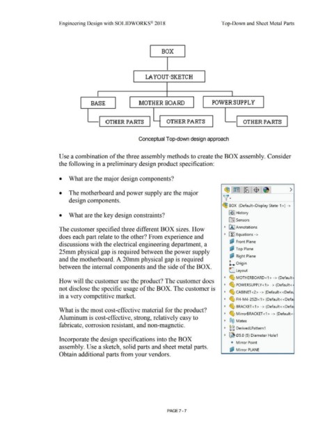
BOX
LA YOUT·SKETCH
BASE MOTHER BOARD POWER SUPPLY
OTHER PARTS OTHER PARTS OTHER PARTS
Conceptual Top-down design approach
Use a combination of the three assembly methods to create the BOX assembly. Consider
the following in a preliminary design product specification:
• What are the major design components?
>
• The motherboard and power supply are the major
design components. -
~ BOX (Default <Display State- 1 >) - >
• What are the key design constraints? ~ I History
t0:I Sensors
The customer specified three different BOX sizes. How • IA] Annotations
does each part relate to the other? From experience and • ~ Equations->
i:JJ Front Plane
discussions with the electrical engineering department, a '
c? Top Plane
25mm physical gap is required between the power supply
i:;? Right Plane
and the motherboard. A 20mm physical gap is required
L Origin
between the internal components and the side of the BOX.
L Layout
• ~ MOTHERBOARD<1 > -> (Default·
How will the customer use the product? The customer does
• ~ POWERSUPPLY<1> -> (Default<·
not disclose the specific usage of the BOX. The customer is
• ~ CABINET <2> -> (Default< <Defa1
in a very competitive market.
• ~ FH-M4-25Zl <1> (Default<<Defa
• ~ BRACKET <1 > - > (Default< <Defa
What is the most cost-effective material for the product?
• ~ MirrorBRACKET <1 > -> (Default <
Aluminum is cost-effective, strong, relatively easy to
• ®@ Mates
fabricate, corrosion resistant, and non-magnetic.
• ~ ~ DerivedLPattern1
• ~ 05.0 (5) Diameter Hole1
Incorporate the design specifications into the BOX
c, Mirror Point
assembly. Use a sketch, solid parts and sheet metal parts.
cP Mirror PLANE
Obtain additional parts from your vendors. '
PAGE 7 - 7