
Page 574 - Subyek Computer Aided Design - [David Planchard] Engineering Design with SOLIDWORKS
P. 574
Top-Down and Sheet Metal Parts Engineering Design with SOLIDWORKS® 2018
BOX Assembly Overview
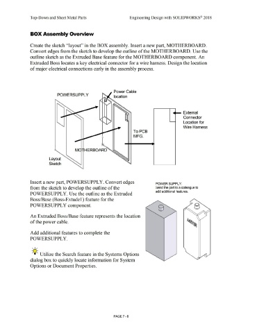
Create the sketch ''layout'' in the BOX assembly. Insert a new part, MOTHERBOARD.
Convert edges from the sketch to develop the outline of the MOTHERBOARD. Use the
outline sketch as the Extruded Base feature for the MOTHERBOARD component. An
Extruded Boss locates a key electrical connector for a wire harness. Design the location
of major electrical connections early in the assembly process.
Power Cable
POWERSUPPL Y
location
- External
Connector
Location for
Wire Harness
To PCB
MFG.
M HERBOARD
Layout
Sketch
Insert a new part, POWERSUPPLY. Convert edges POWER SUPPLY:
from the sketch to develop the outline of the Send the part to a colleague to
add additional features.
POWERSUPPLY. Use the outline as the Extruded
Boss/Base (Boss-Extude 1) feature for the
POWERSUPPL Y component.
An Extruded Boss/Base feature represents the location
of the power cable.
Add additional features to complete the
POWERSUPPLY.
, ,/
-;Q~ Utilize the Search feature in the Systems Options
dialog box to quickly locate information for System
Options or Document Properties.
PAGE 7 - 8