
Page 569 - Subyek Teknik Mesin - Forsthoffers Best Practice Handbook for Rotating Machinery by William E Forsthoffer
P. 569
Be st Practice 1 0.7 The Post-Shipment Phase: Installation, Pre-Commissioning, Commissioning and Start-up Best Practices
1. Clearly stating impact of problem on plant profit
2. Prepare a brief statement of:
The problem
Action plan and confirmation of success (past experience)
Cost of failure to date
Cost of solution
The impact on plant profit (loss)
3. Being confident!
4. Being professional!
5. Providing timely updates and final report on completion
Fig 10.6.24 Obtain and maintain management support by
Best
Best Practice 10.7Practice 10.7Practice 10.7
Best
Implement the following ‘best practice’ oil flushing pro- Lessons Learned
cedure in your plant to produce optimum system cleanli- Most oil flush procedures take too long and are not
ness and minimize flushing time. effective.
Optimal procedures have the following features: Oil flush procedures are rarely performed on time, or result in filter
Nitrogen bubbling cartridge changes (greater than one year multiple when filter differential
Isolation of oil coolers for initial flush exceeded 1.5 bar).
Temporary valved bearing and seal housing bypasses which
maximize oil velocities Benchmarks
Means of ensuring drain lines do not flood during flushing This best practice has been used in varying degrees since nitrogen
Minimizing flush screen number and suggested locations bubbling was demonstrated in the mid-1970s after a refinery fire. It has
Flush screen details to ensure integrity resulted in oil flush times for large equipment trains (greater than 20
Flushing log details for optimum flush effectiveness MW) of less than 2 weeks and filter change-out periods of greater than
1 year.
A proven effective oil flush procedure incorporating the above and
details is contained in the supporting material for this best practice
below.
B.P. 10.7. Supporting Material
Flushing of lube oil and seal oil systems
All critical equipment incorporates bearings that continuously
support the shaft on an oil film approximately 15e20 microns
thick. Even though the lubricating and lube oil systems in-
corporate many components responsible for supply of clean,
cool oil at proper pressure, temperature and flow conditions,
fine debris existing in pipes between flanges and gaskets, in voids
of coolers and other vessels can supply fine metallic and non-
metallic particles that can cause significant damage to bearings
and to the equipment. It is therefore imperative that a cost ef-
fective flushing procedure be implemented in the field. We have
included a cost-effective, proven, oil system flushing procedure
at the end of this section that has repeatedly saved valuable
construction time, and resulted in the cleanest possible oil
system that will minimize filter changes during operation.
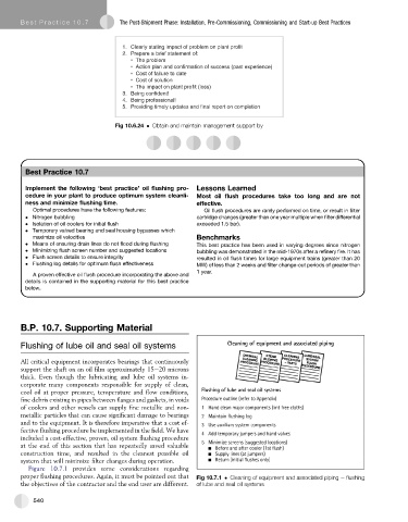
Figure 10.7.1 provides some considerations regarding
proper flushing procedures. Again, it must be pointed out that Fig 10.7.1 Cleaning of equipment and associated piping e flushing
the objectives of the contractor and the end user are different. of lube and seal oil systems
540