Page 575 - Subyek Teknik Mesin - Forsthoffers Best Practice Handbook for Rotating Machinery by William E Forsthoffer
P. 575
Be st Practice 1 0.8          The Post-Shipment Phase: Installation, Pre-Commissioning, Commissioning and Start-up Best Practices
        II Test procedure                                    II Test procedure
          - Take required action to put system in ‘run’ mode   - Confirm all auxiliary systems are operational and at
          - Open trip and throttle valve only after ensuring the main  proper conditions (lined out)
             steam block valve is closed                       - Lube/control oil system
          - Simulate turbine start, slow roll and any start sequence  - Governor/trip system
             ‘hold’ points up to minimum governor operating point  - Turning gear (if applicable)
          - Confirm proper operation of ‘raise’ and ‘lower’ speed  - All warming lines drained and operational
             buttons                                           - Condensing system including condensate pumps (if
          - Connect external process signal inputs (one at a time) and  applicable)
             confirm proper governor action to input signal variation  - Extraction system (if applicable)
          - Check overspeed override feature                   - Steam seal system
          - Confirm automatic transfer to and from backup governor  - Conditionmonitoringsystems(vibration,temperature,etc.)
             ‘position control’ for each of the following cases:  - Steam conditions within allowable vendor limits
               Loss of main governor power supply              - Slow roll and start unit per vendor’s instructions. (refer to
               Zero external input signal                        cold start-up speed vs. time chart)
               Failure of ‘final driver’ (internal governor component)  - Demonstrate manual trip (panic button) at low speed
               Zero speed inputs                                 (500 rpm)
          - Confirm manual transfer to and from backup governor  - Reset trip, accelerate back to desired speed e listen for
             and ‘emergency override’                            rubs, etc.
          - Check raise and lower speed controls while in backup  - Gradually increase speed to next speed step. Record the
             governor mode                                       following data for each vendor required speed step up to
          - Confirm governor shutdown (trip) operation under the  minimum governor speed
             following conditions:                             - Overall vibration at each vibration point (record
               Overspeed setting                                 frequency if specified limits are exceeded)
               Failure of both main and backup governor controls  - Bearing oil temperature rise at each bearing
       III Corrective action                                   - Bearing pad temperature (axial and radial) at each point
          - Failure to meet any requirement in Section II requires  (if applicable)
             corrective action and retest                      - Turbine speed
          - Specifically note corrective action                 - Axial shaft displacement
          - Sign off procedure as acceptable to operate        - Turbine exhaust temperature
                                                                 Note: Use shop test data for comparison
                                                               - After confirming stable operation at minimum governor
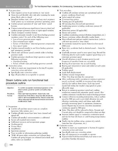
       Steam turbine solo run functional test
                                                                 speed, accelerate carefully to overspeed trip setting
       procedure outline                                         and trip the turbine three times. Each trip speed
                                                                 should fall within the vendor’s trip speed set point
        Objective:  To confirm acceptable mechanical operation of the  allowable range
                    steam turbine, governor system and safety (trip)  - Return to minimum governor speed and confirm
                    system                                       satisfactory manual and automatic speed control. Also
        Procedure   Detail each test requirement. Specifically note
                                                                 confirm automatic transfer from main to backup governor
        Format:     required test limits (Note: shop test data should be
                                                               - Connect vibration recording instruments, reduce turbine
                    used to define acceptable limits). Record actual test
                    values using appropriate instrumentation and note all  speed to 500 rpm and record shaft vibration (at each
                    modifications made.                           vibration monitoring point) and phase angle while
                                                                 gradually increasing speed to maximum continuous
                                                                 speed. Repeat step in reverse direction (maximum
        I Preparation
          - Confirm all auxiliary system tests are complete       continuous speed to 500 rpm)
                                                               - Note: This data will be reduced to Bode, Nyquist and
             (governor, lube system, etc.)
          - Confirm all inlet steam lines have been cleaned and   Cascade plots and should be compared to shop test data.
                                                               - Increase turbine speed to maximum continuous speed
             signed off
          - Confirm all installed instrumentation is calibrated   and run for four (4) hours or until bearing temperatures
          - Secure all required instruments                      stabilize
          - Calibrated pressure and temperature gauges         - Finally trip the turbine using a system trip switch
          - Occiloscope(s)                                       (simulate low oil pressure, etc.)
          - Vector filters                                   III Corrective action
          - Amplifier(s)                                        - Failure to meet any requirement in Section II requires
          - Spectrum analyzer                                    corrective action and retest
          - Tape recorder or information gathering module      - Specifically note any corrective action
          - ‘Walk’ all steam inlet, extraction and exhaust lines.  - Sign off equipment as acceptable to operate
             Confirm all spring hangers are released (unlocked) and  - Typical initial field functional lube/seal system test
                                                                 procedure baseline document
             safety valves are installed

           546

