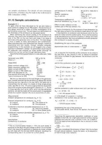
Page 1000 - Industrial Power Engineering and Applications Handbook
P. 1000
An isolated phase bus system  311945
         our sample calculations. For details of  non-continuous   and enclosure (Yo IACS)   60 (at 20"C, Table 30.1)
         encl-osures, reference may be made to the work noted in   Grade          EIE
         IEE Committee (1968).                          Specific resistance       2.873 (at 20°C,
                                                        (P20 in   cm)             Table 30.1)
                                                                                  = 2.873 x   Qcm
         31.13 Sample calculations                      Temperature coefficient of
                                                        electrical  resistance (a2,, in per "C)   3.96 x
                                                                                    (at 20°C, Table 30.1)
         Example 31.1                                   Effect of  solar radiation on the
         To  apply what  we  have discussed  so far  we  give  below a   outdoor part of the bus section ("C)   1 O+
         brief outline of a design for an IPB system. The economics of
         this  design would  be a matter of  further  investigation of  its   Factor of emissivity, for the purpose of heat dissipation for
         performance versus cost. This will require an optimization on   the light grey surface of the enclosure noted above (e) 0.65*
         the thickness  of  the enclosure as discussed earlier.   Cross-sections of  conductor and enclosure are to be the
           When  optimizing the  natural cooling  of  the  enclosure  its   same for indoor and the outdoor parts. This is normal practice
         diameter may have to be increased but this would add to the   of all manufacturers to achieve simplicity in design and ease
         cost  of  the  IPB, on the  one  hand and make it too  large to   of interconnections. We have considered a circular conductor
         terminate at the generator end, on the other. The total design   (the enclosure is usually circular).
         is  thus  a  matter  of  many  permutations  and combinations.
         Most manufacturers have optimized their designs, based on   Establishing the size of  the conductor
         experience  and  test  results,  through  complex  computer               20 000
         programming.  In this example we will suggest only a basic   Approximate area of  cross-section  = -
                                                                                    400
         approach to establish a design. Its optimization would require
         an  elaborate  cost  analysis  as  noted  earlier  although  its        = 50 square inches
         authenticity can be verified through  laboratory tests.   Let us assume the thickness of the conductor to be close to
           Assume the following parameters of a turbo-alternator (Table   but less than 4, say, around 11 mm, to reduce its diameter
         13.8):                                         and hence increase the gap between the enclosure and the
         Generator size (MW)         500 at 50 Hz       conductor.
         Rated p.f.                  0.85               :.  t = 0.43"
                                      500  - 588
         Rated MVA                    --                and for the conductor's outer diameter d,
                                      0.85
         Stator nominal voltage  (kV)   21
         Stator maximum voltage (kV)   24                Area of hollow pipes = E  d,? -  4  dg ]
         Stator current (CMR) (A)     16 200                             4
         Rated current of  IPB (CMR) (A)   18 000
         IPB to be designed for (A)   20 ooo*
         One-second short-time  rating (kA)   122
         Type of  enclosure for IPB   Continuous         50 =  4   (dj + d2)(dl - d2)
           We limit our discussion to the main length of the generator   = rr(d-  0.43) x 0.43
         bus. A similar exercise can be carried out to design the neutral
         shorting star bus, tap-offs to the two  UATs, the delta bus to   _._ d = ___ + 0.43
                                                               50
         interconnect the  GT when  it is  made of  three single-phase   rt x  0.43
         units, tap-offs for CTs, VTs  and surge protective equipment   = 37.46
         and all the auxiliary buses described in Section 31.1.1. Some   and the conductor's outer surface area (no() per foot run
         of these tap-offs, such as for UATs, which are low-rating bus
         sections, can also be made with the construction of segregated   A,,  = K x 37.46 x  12
         phase bus system (Section 28.2.2) to economize on cost.   = 141 1.49 square inches
         Requirements                                   (U is the length of  conductor in inches)
         Ambient temperature for enclosure  (&  in "C)   48   Conductor's  inner surface area per foot  run
         Ambient temperature for conductor  (Oat  in%),   A,,  = ~[37.46 - 2 x 0.431 x  12
                                    1
           for indoors            80  The same as for
           for outdoors           95  the enclosure        = 1379.09 square inches
         Conductor's  maximum allowable temperature  (0, in "C)   Establishing the size of the enclosure
           for indoors            95  Assuming welded
           for outdoors          105 i or silver-plated joints   As discussed above, that thinner the section, the fewer will
         Enclosure's maximum permissible temperature (0, in "C)
           for indoors            80
           for outdoors           95                    +Assuming the  approximate  absorption  coefficient  of  solar
                                                        radiation to be 0.65, for a light-grey external surface, having
         Assumptions                                    collected soot and dirt over a period of  time, as in ANSI-C-
         Conductivity of  conductor                     37-24 the approximate temperature  rise on account of  solar
                                                        radiation
          This is a normal safety margin (=  10%) for such duties.  It
         accounts for the dip in the grid voltage to which it is connected
         which may require the generator to operate at a lower voltage   *We have considered the emission of heat, from the surface
         but still cope with the full-load (MVA) demand, resulting in a   through natural radiation, nearly the same, as its absorption
         corresponding  rise in its current for a short period.   of  heat through solar radiation.

