
Page 1001 - Industrial Power Engineering and Applications Handbook
P. 1001
31/946 Industrial Power Engineering and Applications Handbook
be the losses and the more economical will be the design. - (2.873 C2 cm) x (1' x 12 x 2.54 cm)
x
But we cannot reduce the thickness and increase the diameter
x
of the enclosure indefinitely. A very large diameter may also IT x [(37.46 - 0.43) 2.54 cm] (0.43 x 2.54 cm)
become unsuitable to match at the generator end. The = 0.271 x Rift
generator terminal dimensions, in fact, decide the size of the
enclosure. For the generator rating under consideration, we and
are taking the outside diameter of the enclosure as 1500 mm
(it should be considered according to the site requirement %c105* = RdcPO [l + (lo5 - 20)1
and adjusted for the support insulators selected). The terminal = 0.271 x 10⁻⁶[1 + 3.96 x x 851
spacing of the generator between phases will also determine
the centre spacing of the IPB. In our calculations we assume = 0.271 x [I ,33661
it to be around 68 inches (which may almost be the case in
practice). = 0.3622 x Wft
Enclosure's approximate area of - 20 000 x 0.98 Skin effect ratio, from Figure 31.17 for
-
cross-section 400
= 49 square inches
(assuming the enclosure's current to be around 98% of the = 371.54
conductor's current 0.43
and t/d = -
Enclosure's outer diameter = 1500 mm 37.46
= 0.011
D = 59 inches
:. enclosure thickness t c- 0.27 inch (Figure 31.16) :. Skin effect ratio = 1.03
:. W, (20 000)' x 0.3622 1 0-6 x 1.03
x
=
[49 = n(D - t) . t = IT(= 59)tl
= 149.22 Wlft
:. exact area of cross-section = (59' - (59 - 0.54)') 2 By the enclosure
4
= 49.79 square inches (a) By current
/,)'
Enclosure surface area per foot run A, = x x 59 x 12 W, = (0.98 . RaC
= 2223.12 square inches The current through the continuous enclosure is assumed to
be at about 98% of that of the main conductor. The actual
Checking the suitability of the above sections by current may be less than this as a result of low enclosure
heat balancing thickness, which is considered to be less than the depth of
penetration 4. But it may not cause a high field in the space,
Heat generated (In the outdoor part) leading to heating of steel structures, beams, columns or
1 By the conductor other equipment installed in the vicinity or step and touch
voltages higher than permissible. This is a subject for further
WI = I: R,, W/ft investigation and experiments need be conducted to establish
that the field in the space is within reasonable limits. Otherwise
= I,' Rdc x skin effect ratio the enclosure thickness may need to be increased slightly
and the diameter reduced accordingly.
(2.873 x lo4) (1 x 12 x 2.54)
Now, R,m =
IT x (59 - .27) x 2.54 x 0.27 x 2.54
= 0.273 x aft
and RdcgSt = 0.273 x [l + 3.96 x x (95- 20)]
= 0.273 x 10⁻⁶[1 .297]
= 0.354 x 10⁻⁶ aft
and skin effect ratio from Figure 31.1 7
for jw or 375.8
0.27
59
and tld = - 0.0046
=
*We have the conductor to be operating at its maximum
permissible temperature, although it may be operating at
less than this and generating less heat than assumed.
tHere also we have assumed the maximum operating
temperature although the enclosure may be operating at less
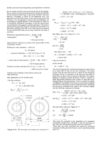
Figure 31.16 IPB conductor and enclosure for Example 31.1 than this.