
Page 1002 - Industrial Power Engineering and Applications Handbook
P. 1002
An isolated phase bus system 31/947
t/ d
0.01 1
4
0.01
5 0.008
a!
0.006
0.0046
I
0.004
1.005 0.002
Jm -
0 50 100 150 200 250 300 350 400 450 500 550 600
&, in .u ST per foot
Note Figure 28.13(b) in RllOOO rn is redrawn in pR/ft.
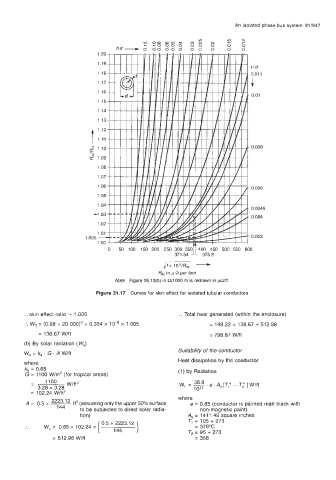
Figure 31.17 Curves for skin effect for isolated tubular conductors
:. skin effect ratio = 1.005 :. Total heat generated (within the enclosure)
:. W2 = (0.98 x 20 000)' x 0.354 x 1 0-6 x 1.005 = 149.22 + 136.67 + 512.98
= 136.67 W/ft = 798.87 wift
(b) By solar radiation (W,)
Suitability of the conductor
W, = k, . G . A Wlft
Heat dissipation by the conductor
where
k, = 0.65 (1) by Radiation
G = 1100 W/m2 (for tropical areas)
- 1100 WlfP 36 9
3.28 x 3.28 W, = -. 10'' e.A,[T: - Ti]Wlff
= 102.24 W/ftz
*
A = 0.5 x ___ ft' (assuming only the upper 50% surface where
e = 0.85 (conductor is painted matt black with
2223.1
144
to be subjected to direct solar radia- nonmagnetic paint)
tion) ] A, = 141 1.49 square inches
.. W, = 0.65 x 102.24 x ( 0.5 ~~22~23.12 TI = 105 + 273
= 378°C
T2 = 95 + 273
= 512.98 Wlft = 368