Page 1003 - Industrial Power Engineering and Applications Handbook
P. 1003
311948  Industrial Power Engineering and Applications Handbook
               36.9                                   where
                   x
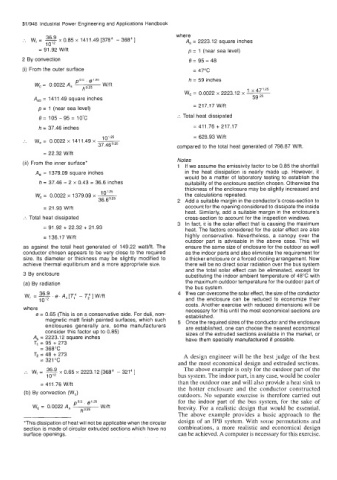
        ...  w,  = - 0.85 x 1411.49 [3784  - 36a4]       A,  = 2223.12 square inches
               1012
             = 91.92 Wlft                                 p = 1 (near sea level)
        2 By convection                                   e=95-48
        (i) From the outer surface                          = 47°C

                        Po-5 ' I9=5                       h = 59 inches
            W, =  0.0022 A,   ho,25   Wlft
                                                         W,  = 0.0022 x 2223.12 x -
                                                                            1
                                                                             X47l.25
           A,,  = 1411.49 square inches                                       59.25
             p = 1 (near sea level)                         = 217.17 Wlft
             e= i05-95=io'c                            :.  Total heat dissipated
             h = 37.46  inches                              = 411.76 + 217.17
                                101.25                      = 628.93 Wtft
        .'.  W,  =  0.0022 x 141 1.49 x   ~
                               37.46°.25               compared to the total heat generated of  798.87 Wlft.
              = 22.32 Wlft
                                                       Notes
        (ii) From the inner surface'
                                                         If we assume the emissivity factor to be 0.85 the shortfall
            Asi = 1379.09 square inches                  in the  heat dissipation is nearly made  up.  However, it
                                                         would be a matter of  laboratory testing to establish the
             h = 37.46 - 2 x 0.43 = 36.6 inches          suitability of the enclosure section chosen. Otherwise the
                                101.25
            W, =  0.0022 x 1379.09 x -                   thickness of the enclosure may be slightly increased and
                                                         the calculations repeated.
                               36.6°.25                  Add a suitable margin in the conductor's cross-section to
              = 21.93 W/ft                               account for the opening considered  to dissipate the inside
                                                         heat. Similarly, add a suitable margin in the enclosure's
        I..  Total heat dissipated                       cross-section to account for the inspection windows.
                                                         In fact, it is the solar effect that is causing the maximum
              = 91.92 + 22.32 + 21.93                    heat. The factors considered for the solar effect are also
              = 136.17 Wlft                              highly conservative.  Nevertheless, a  canopy over  the
                                                         outdoor part  is advisable in the  above  case.  This will
        as against the total heat generated of  149.22 wattlft. The   ensure the same size of enclosure for the outdoor as well
        conductor chosen appears to be very close to the required   as the indoor parts and also eliminate the requirement for
        size.  Its diameter or thickness may be slightly modified to   a thicker enclosure or a forced cooling arrangement. Now
        achieve thermal equilibrium and a more appropriate size.   there will be no direct solar radiation over the bus system
                                                         and the total solar effect can be eliminated, except for
        3 By enclosure                                   substituting the indoor ambient temperature of 48°C with
        (a) By radiation                                 the maximum outdoor temperature for the outdoor part of
                                                         the bus system.
             36.9                                        If we can overcome the solar effect, the size of the conductor
         W,  =-.e.AS[T,4-T:]W/ft
             10'2                                        and  the  enclosure can  be  reduced to  economize their
        where                                            costs. Another exercise with reduced dimensions will be
                                                         necessary for this until the most economical sections are
            e = 0.65 (This is on a conservative side. For dull, non-   established.
               magnetic matt finish painted surfaces, which such   Once the required sizes of the conductor and the enclosure
               enclosures  generally  are,  some  manufacturers   are established, one can choose the nearest economical
               consider this factor up to 0.85)          sizes of the extruded sections available in the market, or
           A,  = 2223.1 2 square inches                  have them specially manufactured if possible.
           TI  = 95 + 273
             = 368°C
            T2  = 48 + 273                               A design engineer will be the best judge of the best
             = 321°C
                                                       and the most economical design and extruded sections.
               36.9                                      The above example is only for the outdoor part of the
         :.  W, =  - x 0.65 x 2223.12 [3684 - 321"]
               10l2                                    bus system. The indoor part, in any case, would be cooler
             = 411.76  Wlft                            than the outdoor one and will also provide a heat sink to
                                                       the  hotter  enclosure  and  the  conductor  constructed
        (b) By convection (W,)
                                                       outdoors.  No  separate exercise is therefore  carried out
                                                       for the indoor part of  the bus system,  for  the  sake of
                        PO5 .
           W,  = 0.0022 A,   ho,25   Wlft              brevity.  For  a realistic design that  would be essential.
                                                       The  above example  provides  a basic  approach  to the
        'This dissipation of heat will not be applicable when the circular   dcsign of an IPB  system. With some permutations and
        section is made of circular extruded sections which have no   combinations,  a more realistic and economical  design
        surface openings.                              can be achieved. A computer is necessary for this exercise.

