
Page 509 - Industrial Power Engineering and Applications Handbook
P. 509
Instrument and control transformers: application and selection 151483
R Y B N
I I I I Stabilizing
resistors
(1450 R each
for example 15.6)
Non-linear
resistors
Figure 15.27 Three-element high-impedance circulating
current relay scheme
maximum value of the stabilizing resistance to be supplied
will depend upon the type of protection (ground or phase
or both) and the relay setting. Generally, it may vary
from SO to IS00 Q.
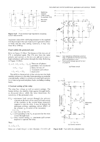
Fault within the protected zone
Refer to Figure 15.28(a). The balance of the two sets of
CTs is disturbed again. The CTs now have the same
polarity and currents as the two sets add up to cause a High impedance differential protection
high-imbalance spill current through the relay. Referring relay. It operates for the fault occurring
within the protection zone
to Figure 15.28(b), Fault current through ground for fault
on phase B
I,, = I,, + 12 = (1\P - I,,,?) These are all phasor
quantities, but considered (a) Power circuit
1
+ (I,,, ~ I,,, linear, for ease of
illustration and without
= 142 + I,,, - 21,n 1 much error
The additive characteristic of the scheme now has high
stability and prevents the relay from operating on moderate
external faults, while it is sensitive to small spill currents
for all internal ground and phase faults, including winding FIL-/
faults.
2 Current setting of the relay
The relay has voltage as well as current settings. The
former defines the stability limit against through-faults,
as discussed above, while the latter determines the
sensitivity of the protected zone.
If IPf = minimum fault current through the primary
(chosen on the basis of the rated full-load current
of the machine or the system being protected) Differential
required to trip the relay. It may be termed the relay
minimum primary operating current (POC) of
the scheme. Ipf, In terms of the secondary
= n x I,f
IZ = turn ratio of the CTs
I,, = corresponding to the V,, to account for the most
severe through-fault
I,, = relay current setting, i.e. minimum spill current
required to operate the relay
I
Then L2 4, = IC2 + 41
- - - (b) Control scheme
I,, = I,, + I,,
Since on a fault the p.f. is low (Section 13.4.1(5)) all Figure 15.28 Fault within the protected zone