
Page 512 - Industrial Power Engineering and Applications Handbook
P. 512
15/486 Industrial Power Engineering and Applications Handbook
10 x 103 2 Relay current setting
I, = 7 Considering a ground circuit resistance of, say, 2 R:
%I3 x 3.3
3.3 x 1000
= 1750 A :. I, =
45 x 2
The fault level of the system, where /g is the ground fault current
100
I,, = 1750 x - (equation (13.5)) = 952.6 A (say 950 A)
10.8
= 16.20 kA Let us consider a setting of, say, 30% of Ig:
... = 0.3 x 950
(Assume a lower value of x; (12 - 1.2 = 10.8%) to be on the /,f
safe side.) = 285 A
Consider CTs with a ratio of 2000/1 A and having R,, = 7 R Referring to Figure 15.28(a) the number of CTs that will fall
and the magnetizing chracteristics as in Figure 15.31. Consider in parallel,
a lead resistance from CT terminals to the relay to be 0.5 R
per lead. N=6
:. Total lead resistance, R, = 2 x 0.5 and Im corresponds to the relay voltage setting of 65 V from
the curve of Figure 15.31 = 15 mA.
= 1 R (presuming this to be at From equation (15.1)
the operating temperature)
285 = 2000 (6 x 0.015 + ISt)
Fault current in terms of the secondary,
:. I*t = ~ 285 - 6 x 0.015
1
is, = 16200 x - 8.1 A 2000
=
2000 = 0.1425 - 0.09
1 Relay voltage setting (stability limit)
= 0.0525 A
V,, = isc(RCT + R,) (considering the resistances at the operating
temperature) Therefore the relay can be set between 5-7.5% of 1 A.
= 8.1 (7 + 1) 3 Stabilizing resistance
Total desired relay circuit impedance
= 64.8 V
say, 65 V or nearest higher setting available on the relay.
:. Minimum kpv, V, = 2 x 65
- 65 - 1238R
= 130 V 0.0525
Relay resistance
R - VA - = L
r-
I:; (0.0525)'
= 363 R
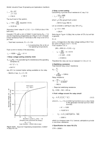
Knee point
:. Required stabilizing resistance
R,t =I238 - 363 = 875 R
/I where V,, = is, x R, (considering that there are no other feeds
4 Peak voltage across the relay circuit
v,= 2
J
&
(1 5.2)
m
to the generator internal fault from other
sources)
= 8.1 x 1238
I
I
I
I I
I
= 10,027.8 V
:. V, = 2&,,/130(10,027.8 -130)
15 I, 1.5/, = 3208 V
Excitation current I,,, (mA) +
(Ampere-turns converfed into Amps.) which is a marginal case. It is, however, advisable to provide
RCT = 7 Cl a non-linear resistance.
Core material - CRGO silicon steel
5 Specification for class PS CTs
Figure 15.31 Assumed magnetizing characteristic of 2000/1
A class PS CTs CTR = 2000/1