
Page 514 - Industrial Power Engineering and Applications Handbook
P. 514
15/488 Industrial Power Engineering and Applications Handbook
Rr =s
1
I Knee ooint I Relay resistance,
= 100 R
(for the same relay as in the earlier example)
:. Required stabilizing resistance,
R,t = 1550 - 100 = 1450 R
4 Peak voltage across the relay circuit
Vk = 310 V
V, = is, R,
= 13.3 x 1550
= 20,615 V
Excitation current lm (mA) - :. V, = 27/1,/310(20,615 - 310)
= 7095 V
0 20 I, 1.51,
(Ampere-turns converted into Amps.) which is more than 3 kV. Hence, a non-linear resistance will
be necessary across the relay branch and must be ordered
from the manufacturer with the relay.
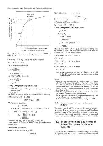
Figure 15.33 Assumed magnetizing characteristic of 3000/ 1 A
class PS CTs 5 Specification for class PS CTs
CTs : 33 kV
For all the CTs let R,, = 10 R and lead resistance
CTR = 1000/1 A Qty 3 numbers
Ri = 0.75 x 2 = 1.5 R
CTs : 11 kV
The fault level of the system
CTR = 3000/1 A Qty 21 numbers
750
Is, = 1.732 x 11 Vk 2 310 V
I, = as low as possible, but not more than 20 mA at 155
= 39 (say 40 kA) V. The CT manufacturer must provide the magnetizing
and in terms of the secondary characteristics.
is, = 40 x - Notes
lo3
xl
3000 1 In the above case the incoming feeder would trip, even
= 13.3 A when the fault occurs in any of the outgoing feeders, which
may not be desirable. It is therefore recommended that
1 Relay voltage setting (stability limit) this scheme be applied to individual feeders, so that in
V,, = 13.3 (1 0 + 1.5) (considering the resistance at the operating case of a fault, only the faulty feeder is isolated rather than
temperature) the whole system.
= 152.95 V 2 With the relay one should also order from the manufacturer
say, 155 V or nearest higher setting available on the relay. (a) Stabilizing resistance of 1450 R and
(b) A non-linear resistance to discharge the excess induced
:. Minimum kpv, V, = 2 x 155 e.m.f., across the relay circuit.
Both these resistances are illustrated in Figure 15.27.
= 310 V (Figure 15.33)
2 Relay current setting. 15.6.7 Core-balanced current transformers
(CBCTs)
Ipf 656.25 A
=
I,,, at 155 V = 20 mA from the curve of Figure 15.33 These are protection CTs and are used for ground leakage
protection. They are also a form of summation CTs, where
.. 656.25 = 3000 (7 x 0.02 + Ist) the phasor sum of the three phase currents is measured.
or ISt = 656.25 -7 x 0.02 The phasor difference, if any, is the measure of a ground
leakage in the circuit. They are discussed in Section 21.5.
3000
= 0.0788A
Therefore, the relay can be set, say, at 10% of 1 A. 15.7 Short-time rating and effect of
The scheme is suitable to detect both a ground fault and
a phase fault. momentary peak or dynamic
3 Stabilizing resistance currents
Relay circuit impedance, R, = -
155
0.1 The normal practice of users when selecting a measuring
= 1550 R or a protection CT has been to specify only the current