
Page 515 - Industrial Power Engineering and Applications Handbook
P. 515
Instrument and control transformers: application and selection 15/489
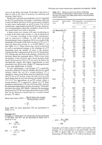
ratio and the likely maximum VA burden it may have to Table 15.11 Maximum short-time factors obtainable
feed as well as the class of accuracy for metering and economically corresponding to rated output, accuracy class,
accuracy limit factor. accuracy limit factor and rated short-time for wound primary
current transformers
Fault level is normally not mentioned, nor is it requested
by the CT manufacturer. Generally, it should be sufficient
to meet the likely fault level of the system and its duration Accuracy Rated output STF obtainable, corresponding to the
rated short times up to
class
VA
in most cases, particularly on an LT system. For critical
installations, large feeders and all HT systems, however, 0.5 s 1.0 s 3.0 s
it is recommended to check the suitability of the CTs for
the system fault level and its duration. (A) Measuring CTs
A short-circuit on a system will cause overheating as 0.5 2.5 1100 115 450
a result of the short-time current, Isc, and its duration of 5 750 525 300
1 or 3 seconds, according to the system requirements 10 500 350 200
and its protective scheme. It will also develop 15 315 215 150
15
200
125
electrodynamic forces (equation (28.4)) as a result of the 1 30 1100 775 450
2.5
momentary first peak of the fault current (in CTs it is 2.5 5 1000 700 400
times the short-time current, Isc, as in IEC 60044-1; see 10 675 415 275
also Table 13.11). These forces may result in electrical 15 500 350 200
as well as mechanical damage to the windings of a CT 3 30 215 200 110
depending upon the number of turns in the primary 2.5 1100 115 450
winding and the configuration of the coil. For bar primary 5 1000 100 400
CTs, having only one turn in the primary, such forces are 10 675 475 215
200
350
15
500
the least, hence the statement above. With a lower class 30 215 200 110
of accuracy, a low VA level, and a lower accuracy limit
factor (for protection CTs) a CT can easily be built to be (B) Protection CTs
mechanically rugged. But higher requirements of such 5P 10 2.5 550 400 225
5
parameters may necessitate a bulky CT, disproportionate 10 375 275 150
150
225
90
in size and cumbersome to install. 15 150 100 60
In most applications, a bar primary CT is generally 30 - - -
used and a normal CT may be suitable. But for too small 5P15 2.5 325 250 135
ratings, where the use of a wound primary CT is 5 215 200 110
imperative, short-circuit effects must be considered, except 10 150 100 60
the CTs for an LT system, where the fault level for such 15 85 60 35
-
-
-
small ratings may be very low and may not matter (Section 5P20 30 325 250 135
2.5
13.4.1(5)). For applications on an HT system, where a 5 200 125 15
wound primary CT is imperative, choice of a CT from 10 100 75 40
standard wound primary CTs may still be possible, meeting 15 - - -
the minimum requirements of class of accuracy, VA burden 30 - - -
and short-time rating. IEC 60044-1 indicates for measuring 10P5 2.5 1000 700 400
and protection CTs the maximum short-time factors (STF) 5 750 525 300
that can be obtained economically for a normal wound 10 425 300 175
15
primary CT where 30 375 215 150
100
60
150
600
Short-time factor (STF) = Rated short-time current lOPl0 2.5 425 425 250
300
175
5
Rated primary current
10 215 200 110
15 200 125 15
Is,
-- 30 - - -
-
I, 10P20 2.5 325 225 125
Some STFs for more important CTs are reproduced in 5 215 200 110
Table 15.11. 10 125 75 50
15 85 60 35
30 - - -
Example 15.7
Consider a 1.5 MVA 33/11 kV transformer having a fault level
of 750 MVA. The STF can be calculated as below with a
circuit of 11 kV: :. STF= 40 x 1000
750 79
Isc = ~ = 506
ax 11
= 40 kA Consider a CT with a ratio of 100/5 A and select a bar
and I,= ~ 1.5 x 1000 primary CT. If a bar primary is not practicable, then for
ax 11 an STF of almost 500, we can choose a wound-type
79A measuring CT from Table 15.11 with an accuracy class