
Page 517 - Industrial Power Engineering and Applications Handbook
P. 517
Instrument and control transformers: application and selection 15/491
4 One should select a lower secondary current, say, 1 A
CT, for installations requiring long lengths of connec-
ting leads, such as for remote measurement of current
or other quantities. It is advisable to limit the extra
VA burden on the CTs, on account of such leads.
**
0.3 R
SECTION 111: TESTING OF
INSTRUMENT AND CONTROL
TRANSFORMERS
I
Excitation circuit
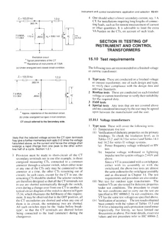
*Typical parameters of the CT 15.1 0 Test requirements
**
Resistance of instruments of 7 5VA
(a) Under energized and closed circuit condition The following tests are recommended on a finished voltage
current transformer:
-- -
Z, = 103 23 kQ - 1.0R Type tests These are conducted on a finished voltage
393 7A u or current transformer, one of each design and type,
to verify their compliance with the design data and
relevant Standards.
Routine tests These are conducted on each finished
voltage or current transformer to verify their suitability
for the required duty.
Field tests
Special tests Any tests that are not covered above
and are considered necessary by the user may be agreed
upon between the manufacturer and the user.
* Approx. impedance of the excitation circuit.
(b) Under energized but open circuit condition.
15.10.1 Voltage transformers
CT circuit referred to the Secondary side.
1 Type tests These will cover the following tests:
(i) Temperature rise test
(ii) Verification of dielectric properties on the primary
windings; To check the insulation level, as in
likely that the induced voltage across the CT open terminals Tables 13.2 and 14.3 for series IandTables 14.1
may give a further momentary kick upto 242 times the voltage and 14.2 for series I1 voltage systems.
calculated above, as the current and hence the voltage shall
undergo a rapid change from one peak to the other within (a) Power frequency voltage withstand or HV
one half of a cycle, Section 1.2.1. test.
(b) Impulse voltage withstand or lightning
3 Provision must be made to short-circuit all the CT impulse test for system voltages 2.4 kV and
secondary terminals not in use (for example, in three above.
energized measuring CTs, connected to a common Since a VT is associated with a switchgear,
ammeter through a selector switch, when either none either with its assembly or with the
or any one of the CTs only may be connected to the switchyard. the above two tests are almost
ammeter at a time, the other CTs remaining out of the same asthoseforthe switchgear assembly
circuit). In such cases, except for the CT in use, the and as discussed in Chapter 14. The test
remaining CTs should be shorted. The selector switches requirements and procedure are also similar.
are therefore designed so that all the CT terminals not (iii) Wet test for outdoor type transformers The
in use are shorted automatically through the switch, outdoor VTs are also tested for dielectric properties
even during a change-over from one CT to another. A under wet conditions. The procedure to create
typical circuit diagram of the switch is shown in Figure the wet conditions and to carry out the test are
15.34, which illustrates the fulfilment of this require- specified in IEC 60060-2. In wet conditions, the
ment. It may be observed that in the OFF position, all VT has the same test voltages as specified above.
the CT secondaries are shorted and when any one of (iv) Verification of accuracy The test results obtained
them is in circuit, the remaining two are shorted. must comply with the values of Tables 15.5 and
All such switches must be the ‘make before break- 15.6 for a measuring and a protection transformer
type’, so that the CT terminals are shorted before respectively. For brevity, we have limited our
being connected to the load (ammeter) during the discussions as above. For more details, exact test
changeover. values and test procedure refer to IEC 60044-2.