
Page 859 - Industrial Power Engineering and Applications Handbook
P. 859
Making capacitor units and ratings of switching devices 25/813
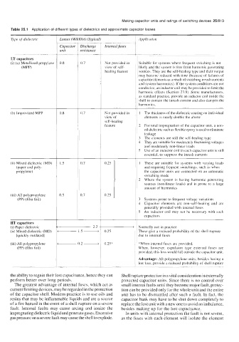
Table 25.1 Application of different types of dielectrics and approximate capacitor losses
Type of dielectric Losses ( W/kVAr) (Typical) Application
Capacitor Discharge Internal fuses
unit resistance
LT capacitors
(i) (a) Metallized propylene 0.8 0.7 Not provided in Suitable for systems where frequent switching is not
(MPP) view of self- likely and the system is free from harmonic generating
healing feature sources. They are the self-healing type and their output
may become reduced with time (because of failures of
capacitor elements as a result of switching inrush currents
and system harmonics). If the system conditions are not
conducive, an inductor coil may be provided to limit the
harmonic effects (Section 23.9). Some manufacturers,
as standard practice, provide an inductor coil inside the
shell to contain the inrush current and also dampen the
harmonics.
(b) Improvized MPP 0.8 0.7 Not provided in 1 The thickness of the dielectric coating on individual
view of elements is nearly double the above
self-healing
feature 2 For total impregnation of the capacitor unit, a non-
oil dielectric such as flexible epoxy is used to eliminate
leakage
3 The elements are still the self-healing type
4 They are suitable for moderately fluctuating voltages
and moderately non-linear loads
5 Use of an inductor coil in each capacitor unit is still
essential, to suppress the inrush currents
(ii) Mixed dielectric (MD) 1.5 0.7 0.25 1 These are suitable for systems with varying loads
(paper and poly- and requiring frequent switchings, such as when
propylene) the capacitor units are connected on an automatic
switching mode
2 Where the system is having harmonic generating
sources (non-linear loads) and is prone to a large
amount of harmonics
(iii) All polypropylene 0.5 0.7 0.25
(PP) (film foil) 3 Systems prone to frequent voltage variations
4 Capacitor elements are non-self-healing and are
generally provided with internal fuses
5 An inductor coil may not be necessary with such
capacitors
HT capacitors 1.5 -
(i) Paper dielectric 2.2 Normally not in practice
(ii) Mixed dielectric (MD) 0.25 These give a reduced probability of the shell rupture
[quickly outdated] 0.2 - due to internal fuses
(iii) All polypropylene 0.25* *When internal fuses are provided.
(PP) (film foil) When, however, expulsion type external fuses are
provided, this loss would fall outside the capacitor unit.
Advantage: All polypropylene units, besides having a
low loss, provide a reduced probability of shell rupture
the ability to regain their lost capacitance, hence they can Shell rupture protection is a vital consideration in externally
perform better over long periods. protected capacitor units. Since there is no control over
The greatest advantage of internal fuses, which act as small internal faults until they become major fault, protec-
current limiting devices, may be regarded in the protection tion can be provided only for the whole unit and the entire
of the capacitor shell. Modern practice is to use oils and unit has to be dismantled after such a fault. In fact, the
resins that may be inflammable liquids and are a source capacitor bank may have to be shut down completely to
of a fire hazard in the event of a shell rupture on a severe replace the lost unit with a new one to avoid an imbalance,
fault. Internal faults may cause arcing and ionize the besides making up for the lost capacitance.
impregnating dielectric liquid and generate gases. Excessive In units with internal protection the fault is not severe,
gas pressure on a severe fault may cause the shell to explode. as the fuses with each element will isolate the element