
Page 861 - Industrial Power Engineering and Applications Handbook
P. 861
Making capacitor units and ratings of switching devices 25/815
25.4.2 Protection of capacitor elements
Capacitor Discharge
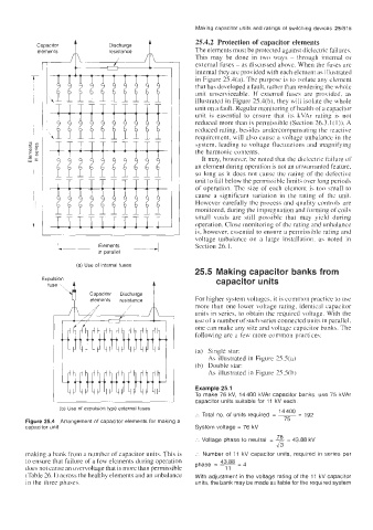
elements resistance The elements must be protected against dielectric failures.
This may be done in two ways - through internal or
external fuses - as discussed above. When the fuses are
internal they are provided with each element as illustrated
in Figure 25.4(a). The purpose is to isolate any element
that has developed a fault, rather than rendering the whole
unit unserviceable. If external fuses are provided, as
illustrated in Figure 2S.4(b), they will isolate the whole
unit on a fault. Regular monitoring of health ofa capacitor
unit is essential to ensure that its kVAr rating is not
reduced more than is permissible (Section 26.3.1 ( 1 )). A
reduced rating, besides undercompensating the reactive
requirement, will also cause a voltage unbalance in the
system, leading to voltage fluctuations and magnifying
the harmonic contents.
It may, however, be noted that the dielectric failure of
an element during operation is not an unwarranted feature,
so long as it does not cause the rating of the defective
unit to fall below the permissible limits over long periods
of operation. The size of each element is too small to
cause a significant variation in the rating of the unit.
However carefully the process and quality controls are
monitored, during the impregnation and forming of coils
small voids are still possible that may yield during
operation. Close monitoring of the rating and unbalance
is, however, essential to ensure a permissible rating and
- Elements 4 voltage unbalance on a large installation. as noted in
Section 26.1.
I
in parallel
(a) Use of internal fuses
25.5 Making capacitor banks from
Ex p u I s i o n capacitor units
fuse 4
Capacitor Discharge
elements resistance For higher system voltages, it is common practice to use
more than one lower voltage rating, identical capacitor
units in series, to obtain the required voltage. With the
use of a number of such series connected units in parallel,
one can make any size and voltage capacitor banks. The
following are a few more common practices:
(a) Single star:
As illustrated in Figure 2SS(a)
(b) Double star:
As illustrated in Figure 2S.S(b)
Example 25.1
To make 76 kV, 14400 kVAr capacitor banks, use 75 kVAr
capacitor units suitable for 11 kV each.
(b) Use of expulsion type external fuses
'4400 = 192
:. Total no. of units required = ~ 75
Figure 25.4 Arrangement of capacitor elements for making a
capacitor unit System voltage = 76 kV
76
=
:. Voltage phase to neutral = - 43.88 kV
43
making a bank from a number of capacitor units. This is :. Number of 11 kV capacitor units, required in series per
43.88 -
to ensure that failure of a few elements during operation phase = -
-
does not cause an overvoltage that is more than permissible 11
(Table 26. I ) across the healthy elements and an unbalance With adjustment in the voltage rating of the 11 kV capacitor
in the three phases. units, the bank may be made suitable for the required system