
Page 862 - Industrial Power Engineering and Applications Handbook
P. 862
25/81 6 Industrial Power Engineering and Applications Handbook
Parallel
group = N2 R,
Series Series
reactor reactor
JRl+n
1111 1111
1111 1111
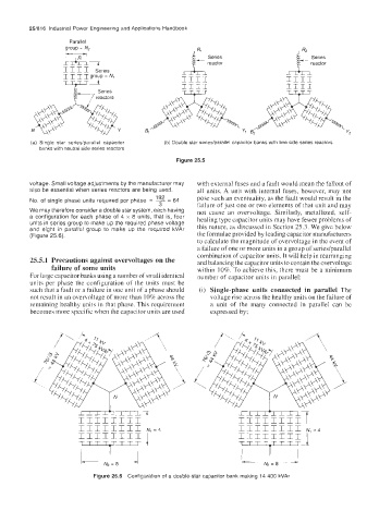
(a) Single star seriesiparallel capacitor (b) Double star series/parallel capacitor banks with line side series reactors
banks with neutral side series reactors
Figure 25.5
voltage. Small voltage adjustments by the manufacturer may with external fuses and a fault would mean the fallout of
also be essential when series reactors are being used. all units. A unit with internal fuses, however, may not
192 pose such an eventuality, as the fault would result in the
No. of single phase units required per phase = - 64
=
3 failure of just one or two elements of that unit and may
We may therefore consider a double star system, each having not cause an overvoltage. Similarly, metallized, self-
a configuration for each phase of 4 x 8 units, that is, four healing type capacitor units may have fewer problems of
units in series group to make up the required phase voltage this nature, as discussed in Section 25.3. We give below
and eight in parallel group to make up the required kVAr
(Figure 25.6). the formulae provided by leading capacitor manufacturers
to calculate the magnitude of overvoltage in the event of
a failure of one or more units in a group of series/parallel
combination of capacitor units. It will help in rearranging
25.5.1 Precautions against overvoltages on the and balancing the capacitor units to contain the overvoltage
failure of some units within 10%. To achieve this, there must be a minimum
For large capacitor banks using a number of small identical number of capacitor units in parallel:
units per phase the configuration of the units must be
such that a fault or a failure in one unit of a phase should (i) Single-phase units connected in parallel The
not result in an overvoltage of more than 10% across the voltage rise across the healthy units on the failure of
remaining healthy units in that phase. This requirement a unit of the many connected in parallel can be
becomes more specific when the capacitor units are used expressed by;
-7
IIIIIIII
Figure 25.6 Configuration of a double-star capacitor bank making 14 400 kVAr