
Page 864 - Industrial Power Engineering and Applications Handbook
P. 864
25/81 8 Industrial Power Engineering and Applications Handbook
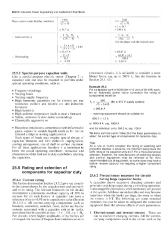
7200
Phase current under healthy conditions ~
ax76 x 76
~
= 2 x 54.7
1 = 54.7 A = 109.4 A
3,N, .Nz
:. Fault current, If
(3N, - 2) 'Ic
1 (for the phase with the faulted unit)
- 3x4x8 x6.82
(3 x 4 - 2)
= 65.47 A
65.47
:. Overloading -- - 65.47 + 54.7
54.7 109.4
1 = 19.7% = 9.84 %
25.5.2 Special-purpose capacitor units electronics circuits, it is advisable to consider a more
Like a special-purpose electric motor (Chapter 7) a liberal factor, say, up to 200% I,.. See the footnote in
capacitor unit can also be required to perform under Section 26.1.1(3).
special operating conditions, such as:
Example 25.3
Frequent switchings For a capacitor bank of 500 kVAr in 10 units of 50 kVAr each,
Varying loads for an automatic power factor correction the rating of
Varying supply frequency components would be
High harmonic quantities (as for electric arc and I, = 500 (for a 41 5 V supply system)
resistance welders and electric arc and induction fi x 0.415
furnaces) = 695.6 A
High humidity
High ambient temperature (such as near a furnace) :. Incoming equipment should be suitable for
Saline, corrosive or dust-laden surroundings
Chemically aggressive or 695.6 x 1.5 A
or 1043.4 A, say, 1000 A
Hazardous installations, contaminated with inflammable and for individual units 104.3 A, say, 100 A
gases, vapour or volatile liquids (such as for marine
(aboard a ship) or mining applications) We have summarized in Table 25.2 the basic parameters to
Such types of loads may require special design of select the correct type of components for capacitor duty.
capacitor elements and their dielectric impregnation,
cooling arrangement, size of shell or surface treatment. Note
For all these applications therefore it is important to As a rule of thumb consider the rating of switching and
protective devices in amperes, the minimum being twice the
know the actual operating conditions, behaviour and kVAr rating of the capacitor units in LT. For a more economical
characteristic of the load and its duty cycle before selecting selection, however, the manufacturers of switching devices
the capacitors. and control equipment may be referred to for their
recommended size of equipment, as some sizes may have a
built-in reserve capacity not requiring a higher component
25.6 Rating and selection of rating.
components for capacitor duty
25.6.2 Precautionary measures for circuits
25.6.1 Current rating having large capacitor banks
The factors discussed in Section 23.5.2 give rise directly A capacitor draws excessive charging currents and
to the current drawn by the capacitor unit and indirectly generates switching surges during a switching operation.
add to its rating. The relevant Standards on this device It also magnifies harmonics when harmonics are present
recommend a continuous overload capacity of 30% to in the system. All these are undesirable and may become
account for all such factors. A capacitor can have a hazardous when the banks are large, the more so when
tolerance of up to +15% in its capacitance value (Section the system is HT. The following are home remedial
26.3.1( 1)). All current-carrying components such as measures that can be taken to safeguard the connected
breakers, contactors, switches, fuses, cables and busbar equipment from the adverse effects of such parameters:
systems associated with a capacitor unit or its banks,
must therefore be rated for at least 1.3 x 1. 15fc, i.e. 1 SI,. 1 Electrodynamic and thermal stresses These are
For circuits where higher amplitudes of harmonics are due to excessive charging currents. All the current-
envisaged, for reasons of frequent load variations or more carrying components used in the circuit such as the