
Page 879 - Industrial Power Engineering and Applications Handbook
P. 879
Protection, maintenance and testing of capacitor units 261831
Safe zone Zone-1 Zone-2 Hazardous zone Minimum rating of fuses = 200% of lc
--I----
50 i.e. 2 x 6.82 A or 13.64 A
Select from the manufacturer's catalogue 16 A fuses for
each unit, according to the characteristics in Figure 26.2
20 reproduced in Figure 26.3. The fuse characteristics fall well
within the safe zone and provide adequate protection to the
units. If series reactors are provided to control the inrush
10
current, a fuse corresponding to 150% of lc, i.e. of 10 A,
would be better to protect the unit more closely. We can see
from Figure 26.2 that in an internally protected unit the
characteristics of the internal fuses will fall well below that of
an external fuse and provide a more exacting protection on a
mild fault.
4 t:: 7 Voltage transients
These may be caused by internal switchings or external
0
2 lightning strikes. HT capacitor units, particularly. may
z be protected through surge arresters against such voltage
K transients (Chapter 18). The voltage rating of the surge
arrester may be chosen on the following basis:
For ungrounded systemi = V,
01
For grounded systems = 0.8 V,
See also Table 18.2
8 Voltage unbalance
An unbalance in the supply sy\tem causes an okervoltage
0 013
0 01
20 000
3000 1 10000
100 200 300 5001000
10 30 *Fault current (Amp ) rms - 10000
4 hrs
5000
@ - Characteristic of a 10A external fuse from Figure 26 3
0- Characteristic of a 16A external fuse from Figure 26 3
0- Probability curves for case rapture
' Use asymmetrical rms values for transient faults 1000
Figure 26.2 NEMA probability curves for a case rupture and
selection of internal and external fuses
~100
4
rupture is not eliminated. An unbalance protection is a 0
better choice in such cases, which may isolate the faulty E
unit much faster than the luses. When it is so, the units E 10
remain intact. At this stage visual checks can be made to c
2
find all such units that may be excessively hot or have t!
bulged out. The capacitance of the units can also be ?
measured to identify the faulty unit(s) or the extent of 10
damage to individual units and take corrective steps before
reahitching the units. Example 26.1 illustrates a simple
procedure to select external HRC fuses. The fuses are
provided separately for each unit. 01
Example 26.1
Consider the same units as those in Example 25.2 where
V,, of each unit = 11 kV 0 01 RMS symmetrical prospective current (Amp ) -
kVAr = 75 10 10 100 lo00
N1 = 4
N2 = 8
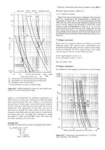
I, = 6.82 A Figure 26.3 Timehrrent characteristics for 11 kV HRC
and If = 65.47 A fuses (Courtesy: GEC Alsthom)