
Page 880 - Industrial Power Engineering and Applications Handbook
P. 880
261832 Industrial Power Engineering and Applications Handbook
across the capacitor units in phases that have a higher (established by the capacitor manufacturers)
voltage. A partial or total failure of a capacitor unit in a where
large capacitor bank will also cause an unbalance and an V,, = unbalance voltage across the open delta. This is
overvoltage across the healthy units connected in parallel. for grounded systems. For isolated systems it will
Such a situation is not desirable, and unless detected be three times this (Section 15.4.3).
promptly, may result in a cascade failure of more units.
It can be detected by the following methods for an alarm,
indication or trip of the entire bank:
N = number of units failed
N, = number of units in series per group per phase
(i) Voltage unbalance N2 = number of units in parallel per group per phase.
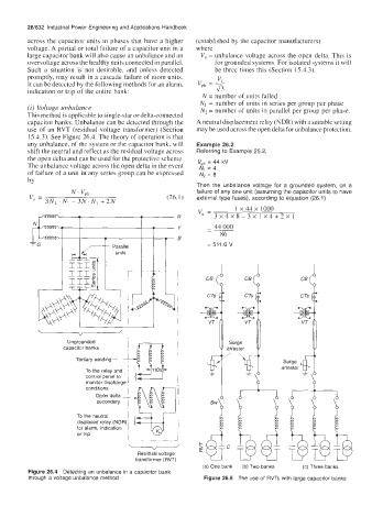
This method is applicable to single-star or delta-connected
capacitor banks. Unbalance can be detected through the A neutral displacement relay (NDR) with a suitable setting
use of an RVT (residual voltage transformer) (Section may be used across the open delta for unbalance protection.
15.4.3). See Figure 26.4. The theory of operation is that
any unhalance, of the system or the capacitor bank, will Example 26.2
shift the neutral and reflect as the residual voltage across Referring to Example 25.2,
the open delta and can be used for the protective scheme.
The unbalance voltage across the open delta in the event V,, = 44 kV
NJ = 4
of failure of a unit in any series group can be expressed N2 = 8
by
Then the unbalance voltage for a grounded system, on a
failure of any one unit (assuming the capacitor units to have
' vph
vu = (26.1) external type fuses), according to equation (26.1)
3N2. Ni - 3N. N, + 2N
vu = 1 x 44 x 1000
3X4X8-3X1X4+2Xl
- 44 000
- 86
= 511.6 V
21
d d
c5
VJ VT
\d
Ungrounded Surge
capacitor banks I arrester
Tertiary winding i
,
Surge
transformer (RVT) " L
I arrester
To the relay and ~
control panel to
monitor discharge 1
conditions 1
To the neutral
Residual voltage
(a) One bank (b) Two banks (c) Three banks
Figure 26.4 Detecting an unbalance in a capacitor bank
through a voltage unbalance method Figure 26.5 The use of RVTs with large capacitor banks