
Page 881 - Industrial Power Engineering and Applications Handbook
P. 881
Protection, maintenance and testing of capacitor units 261833
and for an ungrounded system time delay of a few seconds can be introduced into the
Vu = 3 x 511.6 J 1535 V trip circuit. Sensitivity and the setting of the relay will
depend upon the size of the banks and the sensitivity of
If the ratio of VT is 44 kVillO V, then the voltage across the the system, i.e, whether an alarm or indicator will be
open delta sufficient initially while repairs are undertaken during
~ 1535 x 110 off-peak periods, or whether a trip will be needed. The
44000 amount of unbalance current can be determined by the
=384V following formula:
and suitable NDR may be selected for this voltage (26.2)
For more than one capacitor bank one RVT for each bank
will be necessary for the correct discharge of each bank,
(Figure 26 5) An RVT, if provided with an additional star- (established by the capacitor manufacturers)
connected tertiary winding rated for 110 V line to line, can where I, = imbalance current through the interconnected
also check the discharge condition and its duration and if it neutral, and
meets the design requirements This can even be monitored I, = current per capacitor unit.
remotely through a relay and control panel
Note
Note Current-sensing protection i\ found to be more accurate than a
When an RVT is being used for the purpose of discharge, voltage sensing. It ia therefore recommended that the unit\ are
also no protective fuses are recommended to ensure a positive arranged in double $tar as far as possible.
discharge. On a trip, the RVT is programmed to be connected
automatically to the capacitor units to discharge them.
(iii) Ampere meter mrthod
To monitor the health of a capacitor uiiit il is advisable
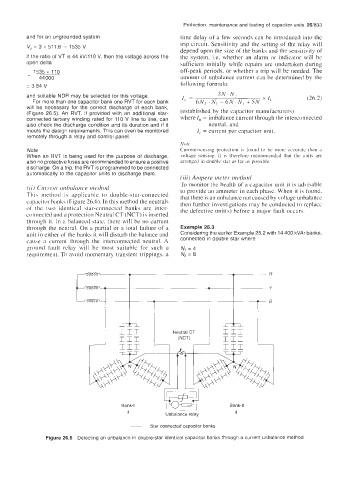
(iij Ciirt.etit iit~brrltrric~ nirthorl to provide an ammeter in each phase. When it i\ found,
Thi\ method is applicable to double-star-connected that there is an unbalance not caused by voltage unbalance
capacitor banks (Figure 26.6). In this method the neutrals then further investigations may be conducted to replace
of the two identical star-connected banks are inter- the defective unit(s) before a major fad^ occurs.
connected and a protection Neutral CT (NCT) is inserted
through it. In a balanced state, there will be no current
through the neutral. On a partial or a total failure of a Example 26.3
unit in either of the banks it will disturb the balance and Considering the earlier Example 25.2 with 14 400 kVAr banks,
taus ;I current through the interconnected neutral. A connected in double star where
ground fault relay will be most suitable for such a N, = 4
requirement. To avoid momentary transient trippings. a N2 = 8
T T R
Bank-ll
Bank-I w L-
~ ~
1 Unbalance relay 1
Star connected capacitor banks
Figure 26.6 Detecting an unbalance in double-star identical capacitor banks through a current unbalance method