
Page 886 - Industrial Power Engineering and Applications Handbook
P. 886
Protection maintenance and testing of capacitor units 261837
/c (fault)
@ Series reactor to add to
E, line impedance
iving end
") Isolators
0
@ Dampening resistor
@ Auxiliary saturating reactor
@ Main saturating discharge reactor
/c(fault) I (fault) ~~~~~~~ ~~ I
An R-L dampening circuit
Figure 26.10 Dampening circuit across the series capacitors to limit the fault level
<@
P
kid
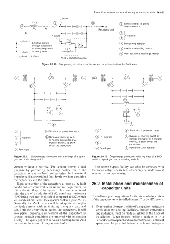
&@ @ Short circuit protection relay
@Short circuit protection relay
0 isolators
@ Bypass or shorting switch (a
E 1 Isolators
@Bypass or shorting switch
normal interrupter or a thyristor
(a normal interrupter or a
switch). to short circuit the
thyristor switch), to short
circuit the capacitors 0 capacitors
@Spark gap @ Spark gap @ Non linear ZnO-resistor
@
Figure 26.11 Overvoltage protection with the help of a spark Figure 26.12 Overvoltage protection with the help of a ZnO
gap and a shorting switch resistor, spark gap and a shorting switch
current without a restrike. The scheme serves a dual The above bypass facility can also be achieved with
purpose by providing necessary protection to the the use of a thyristor switch, which may be made current
capacitors, on the one hand, and restoring the line natural sensing or voltage sensing.
impedance (i.e. the original fault level) by short-circuiting
the capacitors. on the other.
Rapid reinsertion of the capacitors as soon as the fault 26.2 Installation and maintenance of
conditions are removed is an important requirement to capacitor units
retain the stability of the system. This can be achieved
with the use of an additional ZnO. non-linear resistance
(ZnO being the latest in this field compared to Sic, which The following are suggestions for the successful operation
was used earlier). across the capacitor banks (Figure 26.12). of the capacitor units installed on an LT or an HT system:
Generally. the ZnO resistor will be adequate to dampen
the fault current without initiating the spark gap, and 1 Overheating shortens the life of a capacitor. Adequate
will limit the overvoltage across the capacitors. It will ventilation and cooling facilities, through convection
also permit automatic reinsertion of the capacitors as and radiation, must be made available at the place of
soon as the fault conditions are removed without causing installation. When housed inside a cubicle. as in a
a delay. The spark gap will serve as a backup to the ZnO capacitor control panel and in a tier formation, sufficient
resistor in the event of very severe faults. space must be provided between each unit. Adequate