
Page 896 - Industrial Power Engineering and Applications Handbook
P. 896
Power reactors 271847
27.1 Introduction 4 Tap-changing facility Where necessary, the reactance
of the coil can be varied by providing an on- or offload
tap-changing gear with the reactor, similar to a power
Power reactors are similar to transformers. However, they transformer.
have only one winding per phase and can be represented
as shown in Figure 27.1. They are employed to perform
a number of functions, primarily to control and regulate 27.2a Selection of power reactors
the reactive power of a power system by supplying the
inductive and absorbing the capacitive power. Control
can be achieved in different ways as noted later. The When it is required to limit the inrush current a fixed
reactors, depending upon their design and I-@ reactance (linear) reactor is more suitable. A variable
characteristics. can be classified as follows: type reactor will be necessary when it is to be used for
voltage regulation or load sharing. In circuits where
Single- or three-phase Single-phase reactors are harmonics may be present, saturated type reactors may
used in the neutral circuit either to limit the ground be preferred.
fault currents or as arc-suppression coils (Section 20.5). The harmonic content may be measured through
Similarly, three-phase reactors are used for three-phase harmonic analysers and expressed as a percentage of the
applications. fundamental component. The current and voltage ratings
Air-cooled dry type and oil-immersed type This of the reactors will depend upon their application. A
will depend upon the size of the reactor and the design series reactor connected permanently in the circuit, for
of the manufacturer. The latest practice is to use air- instance, will be rated continuously and for full system
cooled dry type, which call for lesser maintenance voltage, whereas a reactor used in the ground circuit
and are free from any fire hazards. may be short-time rated and rated for the likely maximum
Indoor or outdoor types These may be designed ground fault current.
indoor or outdoor types depending upon the application.
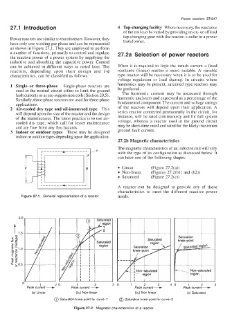
27.21, Magnetic characteristics
The magnetic characteristics of an inductor coil will vary
with the type of its configuration as discussed below. It
can have one of the following shapes:
Linear (Figure 27.2(a))
Non-linear (Figures 27.2(bl) and (b2))
Saturated (Figure 27.2(c))
A reactor can be designed to provide any of these
characteristics to meet the different reactive power
Figure 27.1 General representation of a reactor needs.
Saturation
knee-point
Peak current - \ Non-saturated
region
1 20 1 2 30 1 2 3 40 1 2 3
Peak current + Peak current + Peak current-
(a) Linear (b,) Non-linear (b2) Non-linear (c) Saturated
@ Saturation knee-point for curve-I @ Saturation knee-point for curve-2
Figure 27.2 Magnetic characteristics of a reactor