
Page 897 - Industrial Power Engineering and Applications Handbook
P. 897
27/848 Industrial Power Engineering and Applications Handbook
27.3 Design criterion and I-+ ,
=1
characteristics of different MS tank
types of reactor Grounding
terminal
27.3.1 Air-cored or coreless type reactors
These reactors are made of copper winding without any
core, similar to an air-cored solenoid, as shown in Figure
27.3. In the absence of an iron core it causes a large Magnetic
amount of leakage flux in the space, which may also ,’- shield
infringe with the metallic tank housing the reactor, and
affect the reactance of the coil, in addition to heating the
tank itself. It is therefore important to provide some kind A Copper wound
of shielding between the winding of the reactor and the coil
tank. The shielding can be magnetic or non-magnetic as
discussed later. With shielding, the characteristics of an
air core reactor can be altered according to its application. ,,- Pressing plate
Such reactors provide linear I-$ characteristics in the
operating range, say, up to 150% of the rated current as
shown in Figure 27.2(a). In the absence of an iron core,
there is no saturation of the core. These reactors are y Tie rod
more useful when they are required to be used as current
limiting devices. But they reduce the steady-state power
transfer capability (V,’ /Z) of the system, as discussed in
Section 24.8.
With magnetic shielding
A magnetic circuit develops a stray magnetic field around
it. A reactor, which is a magnetic circuit, at higher currents ,- wound
Copper
such as during switching operations or faults will develop coil
high magnitudes of stray fields around it that may link
magnetic objects in the vicinity and cause high induced M.S tank
e.m.f.s in them, as in nearby metallic structures and
electrical apparatus. All this may result in high circulating
t-
I I
I
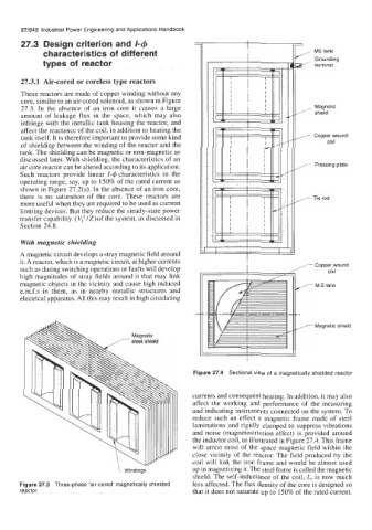
Figure 27.4 Sectional view of a magnetically shielded reactor
currents and consequent heating. In addition, it may also
affect the working and performance of the measuring
and indicating instruments connected on the system. To
reduce such an effect a magnetic frame made of steel
laminations and rigidly clamped to suppress vibrations
and noise (magnetostriction effect) is provided around
the inductor coil, as illustrated in Figure 27.4. This frame
will arrest most of the space magnetic field within the
close vicinity of the reactor. The field produced by the
coil will link the iron frame and would be almost used
Windings up in magnetizing it. The steel frame is called the magnetic
shield. The self-inductance of the coil, L, is now much
Figure 27.3 Three-phase ‘air-cored’ magnetically shielded less affected. The flux density of the core is designed so
reactor that it does not saturate up to 150% of the rated current.