
Page 898 - Industrial Power Engineering and Applications Handbook
P. 898
Power reactors 271849
Any increase in the fundamental value of the current For the theory of neutralization of the magnetic effect
beyond 1 50470, or a voltage drop across the coil of more on the conductor in a non-magnetic shielding, refer to
than 150% of the reactor voltage (this may occur in the the continuous enclosures for isolated phase bus systems
presence of harmonics) may, however, saturate the core discussed in Section 31.2.2. As a result of non-magnetic
and reduce the reactance of the coil. Magnetically shielded shielding there will be no saturation of the iron core and
reactors therefore have limitations when the system the V-I characteristic of the reactor will remain almost
harmonics are high or when linear V-I characteristics linear.
are desirable beyond 150% of the rated fundamental These types of reactors can now be used as current
current. limiting reactors and also as harmonic suppressors. They
The need for a magnetic shielding is greater in high are also recommended for capacitor application due to
current reactors than in smaller ratings. For more details their linear characteristic which will not disturb the tuning
on magnetic shielding see Section 28.2.2 on segregated of the filter circuit.
phase bus systems.
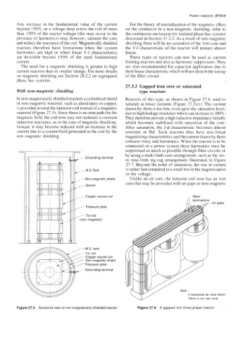
27.3.2 Gapped iron core or saturated
With non-magnetic shielding type reactors
In non-magnetically shielded reactors a cylindrical shield Reactors of this type, as shown in Figure 27.6, tend to
of non-magnetic material, such as aluminium or copper, saturate at lower currents (Figure 27.2(c)). The current
is provided around the inductor coil instead of a magnetic drawn by them is too low, even up to the saturation level,
material (Figure 27.5). Since there is no iron path for the due to high leakage reactance which can increase to 100%.
magnetic field, the coil now may not maintain a constant They therefore provide a high inductive impedance initially
inductive reactance, as in the case of magnetic shielding. which becomes stabilized with saturation of the core.
Instead. it may become reduced with an increase in the After saturation, the I-$ characteristic becomes almost
current due to a counterfield generated in the coil by the constant or flat. Such reactors thus have non-linear
non-magnetic shielding. magnetizing characteristics and the current drawn by them
contains many odd harmonics. When the reactor is to be
connected on a power system these harmonics must be
suppressed as much as possible through filter circuits or
K by using a multi-limb core arrangement, such as the six-
Grounding terminal
or nine-limb zig-zag arrangement illustrated in Figure
27.7. Beyond the point of saturation, the rise in current
- M.S Tank is rather fast compared to a small rise in the magnetization
or the voltage.
- Non-magnetic shield Unlike an air core, the inductor coil now has an iron
core that may be provided with air gaps or non-magnetic
- Spacer
Steel
- Copper wound coil /IT laminations
- , - gaps
Air
i: Pressure plate
,,- tank
M.S.
Non-magnetic shield
/ Note
/ It becomes air core when
there is no iron core
Figure 27.5 Sectional view of non-magnetically shielded reactor Figure 27.6 A gapped iron three-phase reactor