
Page 899 - Industrial Power Engineering and Applications Handbook
P. 899
27/850 Industrial Power Engineering and Applications Handbook
\ Limit the switching surges as discussed in Section
\
\ 23.5.1. But they may affect the steady-state power
transfer capability of the system (V,2/Z). Refer to
reactive power control (equation (24.10)).
Adjust the steady-state voltage control by supplying
reactive power and compensating the capacitive
content.
Suppress the harmonic contents.
Their ratings can be calculated by
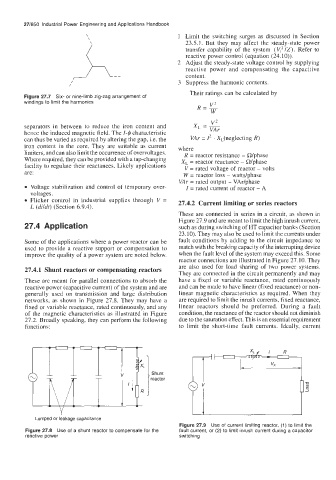
Figure 27.7 Six- or nine-limb zig-zag arrangement of
windings to limit the harmonics V2
R=-
W
V2
separators in between to reduce the iron content and XL =
hence the induced magnetic field. The 1-4 characteristic
can thus be varied as required by altering the gap, i.e. the VAr = I* . XL(neglecting R)
iron content in the core. They are suitable as current where
limiters, and can also limit the occurrence of overvoltages. R = reactor resistance - Wphase
Where required, they can be provided with a tap-changing X, = reactor reactance - Wphase
facility to regulate their reactances. Likely applications V = rated voltage of reactor - volts
are: W = reactor loss - wattdphase
VAr = rated output - VAr/phase
Voltage stabilization and control of temporary over- I = rated current of reactor - A
voltages.
Flicker control in industrial supplies through V = 27.4.2 Current limiting or series reactors
L (dildt) (Section 6.9.4).
These are connected in series in a circuit, as shown in
Figure 27.9 and are meant to limit the high inrush current,
27.4 Application such as during switching of HT capacitor banks (Section
23.10). They may also be used to limit the currents under
Some of the applications where a power reactor can be fault conditions by adding to the circuit impedance to
used to provide a reactive support or compensation to match with the breaking capacity of the interrupting device
improve the quality of a power system are noted below. when the fault level of the system may exceed this. Some
reactor connections are illustrated in Figure 27. IO. They
are also used for load sharing of two power systems.
27.4.1 Shunt reactors or compensating reactors
They are connected in the circuit permanently and may
These are meant for parallel connections to absorb the have a fixed or variable reactance, rated continuously
reactive power (capacitive current) of the system and are and can be made to have linear (fixed reactance) or non-
generally used on transmission and large distribution linear magnetic characteristics as required. When they
networks, as shown in Figure 27.8. They may have a are required to limit the inrush currents, fixed reactance,
fixed or variable reactance, rated continuously, and any linear reactors should be preferred. During a fault
of the magnetic characteristics as illustrated in Figure condition, the reactance of the reactor should not diminish
27.2. Broadly speaking, they can perform the following due to the saturation effect. This is an essential requirement
functions: to limit the short-time fault currents. Ideally, current
AJ- I I V I
Lumped or leakage capacitance
Figure 27.9 Use of current limiting reactor, (1) to limit the
Figure 27.8 Use of a shunt reactor to compensate for the fault current, or (2) to limit inrush current during a capacitor
reactive power switching