
Page 900 - Industrial Power Engineering and Applications Handbook
P. 900
Power reactors 271851
c
T
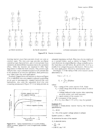
(a) Feeder connections (b) Tee-off connections (c) Busbar sectionalizer connections
Figure 27.10 Reactor connections
limiting reactors must have no-iron circuit (air core or adequate impedance on fault. They may also be employed
coreless type). The iron core type provide non-linear as a current limiter, such as shown in Figure 27.9. It
saturating type characteristics, and at overcurrents have must, however, be ensured that the voltage available across
a tendency to diminish their reactance due to the saturation the load does not fall below the permissible level as a
effect, while the reactors are required to offer high result of the voltage drop across the reactors. The reactors
impedances to limit the fault currents. The coreless type for such applications should be continuously rated.
will provide a near-constant reactance at all currents due For Figure 27.9 the rating of the series reactor can be
to the absence of an iron core and hence, their preference determined by
over other types for such applications.
Similarly, gapped iron core reactors as shown in Figure VAr ' V, I
27.4, in which the iron core content is reduced by providing
"'
an air gap or non-magnetic material between the core x, = - Rlphase
laminations, also raise the saturation level (the core 43.1
remaining unsaturated, Figure 27.1 1) to help provide an where
VAr = rating of the series reactor (Volt. Amp)
V, = rated voltage drop of the reactor phase to phase
in volts
I I = voltage induced in the reactor when operating
at rated current and rated reactance
I = rated current of the reactor (A)
R = resistance of the reactor
.. R << XI- (less than 2-372 of XL) may be ignored
Example 27.1
Consider a three-phase reactor having the following
specifications:
V, = 33 kV
V, = 3% of the system voltage (phase to phase)
System current, I, = 650 A
0 1 2 3 4
Peak current in the --t To determine the size of the reactor
faulty region
V. in absolute terms
3
Figure 27.11 Typical characteristics of a current limiting =-x33
reactor (coreless, gapped iron core or magnetically shielded 100
core type) = 0.99 kV, say 1 kV