
Page 908 - Industrial Power Engineering and Applications Handbook
P. 908
Carrying power through metal-enclosed bus systems 28/859
28.1 Introduction of copper may be more appropriate in highly corrosive
areas.
In humid and corrosive conditions. aluminium erodes
In a power-generating station power is carried from the faster than copper. These solid or hollow conductor5
generator to the power transformer, to the unit auxiliary
transformer (UAT) or to the unit auxiliary switchgear as connect the supply side to the receiving end and are
illustrated in Figure 13.21 through solid conductors (HT called bus ducts. They may be of the open type, such as
are used to feed a very high current at cery low voltage.
bus systems). This is due to large capacity of the generators A smelter unit IS one such application. But normally
(upto 1000 MW). The transmission of such large amounts
of power over long distances is then through overhead they are housed in a sheet metal enclosure. See Figures
28.2(a) and 28.33b).
lines or underground cables. Our main concern here will be dealing with large to
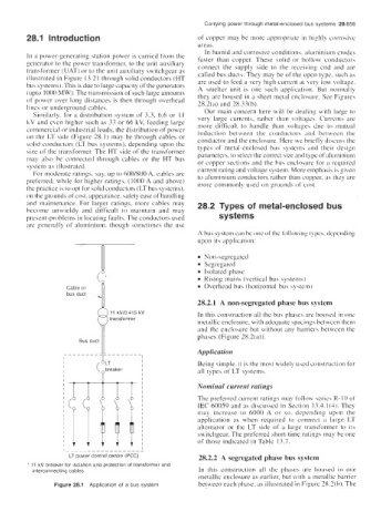
Similarly, for a distribution system of 3.3, 6.6 or 1 I
kV and even higher such as 33 or 66 kV, feeding large very large currents, rather than voltages. Currents are
more difficult to handle than voltage5 due to mutual
cominercial or industrial loads, the distribution of power induction between the conductors and between the
on the LT side (Figure 28.1) may be through cables or conductor and the enclosure. Here we briefly discuss the
solid conductors (LT bus systems), depending upon the typcs of metal-enclosed bus systems and their design
size of the transformer. The HT side of the transformer parameters. to select the correct size and t) pe of aluminium
may also be connected through cables or the HT bus or copper sections and the bus enclosure for a required
system as illustrated. current rating and voltage system. More emphasis is given
For moderate ratings. say. up to 600/800 A, cables are
preferred. while for higher ratings, (1 000 A and above) to aluminium conductors rather than copper. as they are
more commonly used on grounds of cost.
the practice is to opt for solid conductors (LT bus systems),
on the grounds of cost, appearance. safety ease of handling
and maintenance. For larger ratings, more cables may 28.2 Types of metal-enclosed bus
become unwieldy and difficult to maintain and may
present-problems in locating faults. The conductors used systems
are generally of aluminium. though sometimes the use
A bus system can be one ofthe following types. dcpcnding
upon its application:
Non-segregated
Segreg'tted
Isolated phase
Rising main5 (vertical bus system\)
Overhead bus (horizontal bus sy\tcm)
28.2.1 A non-segregated phase bus system
In this construction all the bus phasex are housed in one
metallic enclosure, with adequate spacings between them
_I_ phases (Figure 28.2(a)).
and the enclosure but without any barrier5 between the
Bus duct Application
Being simple, it is the most widely used construction lor
a11 types of LT systems.
Nominal current ratings
The preferred current ratings may follow series K- IO of
IEC 60059 and as discussed in Section 13.4.1(3). They
may increase to 6000 A or so. depending upon the
application as when required to connect a large LT
alternator or the LT side of a large transformer to its
switchgear. The preferred short-time ratings may be one
of those indicated in Table 13.7.
LT power control centre (PCC) 28.2.2 A segregated phase bus system
* 11 kV breaker for isolation and protection of transformer and
interconnecting cables In this construction all the phases are Iiou.secl in one
metallic enclosure as earlier, but with a metallic barrier
Figure 28.1 Application of a bus system between each phase. as illustrated in Figure 28.2(b). The