
Page 985 - Industrial Power Engineering and Applications Handbook
P. 985
311930 Industrial Power Engineering and Applications Handbook
1 CT for protection bonded and the induced currents may not have a
1 CT for AVR (automatic voltage regulator) continuous path.
1 CT for differential protection
For each phase on the neutral side, 1 CT for differential The enclosure, however, should be insulated at all such
protection, two sets of three CTs each for metering, locations, where the IPB terminates with another
in the tap-offs for the two UATs and two sets of three equipment, such as at the generator, GT, UATs, VTs, and
CTs each for protection in the tap-offs for the two the NGT to avoid longitudinal currents through such
UATs. equipment. These equipments are grounded separately.
2 Tap-offs with a neutral CT, from star point of the
generator, to the neutral grounding transformer (NGT).
3 VTs and surge protection tap-offs for each phase from 31.2 Constructional features
the main run, for metering and surge protection.
Any other connections, that may be necessary at site
or additional CTs for protection. As discussed later, the enclosure of an IPB may carry
induced currents up to 95% of the current through the
31.1.3 Shorting of phase enclosures main conductors. Accordingly, the enclosure is designed
to carry longitudinal parasitic currents up to 90-95% of
For continuous enclosure IPBs, the following ends of the rated current of the main busbars. The cross-sectional
the enclosures are shorted to ensure continuous flow of area of the enclosure is therefore maintained almost equal
induced currents: to and even more than the main conductors to account
for the dissipation of heat of the main conductors through
At the generator end, as near to the generator terminals the enclosure only, unless an additional forced cooling
as possible. system is also adopted. The outdoors part of the enclosure
GT ends, as near to the transformer flanges as possible. exposed to atmospheric conditions is also subjected to
UATends. solar radiation. Provision must be made to dissipate this
Both sides of the neoprene or EPDM rubber or metallic additional heat, from the enclosure.
expansion bellows. The main bus and its enclosure is normally in a tubular
Near the generator neutral terminal. form, in view of the advantages of a tubular section, as
Any other section, where it is felt that it is not properly discussed already (concentration of current in the annulus,
$of turbo generatot
of turbo generator
-+-
Generator Indoor Outdoor
I
flange
I I Sealma
I
1.-
I
I TI
4=
I VT, & surge
Neutral
I grounding protection
I transformer cubicle
I Grating floor Bellows assembly
I with seal off
bushing
I
I
I
%%& Turbine room
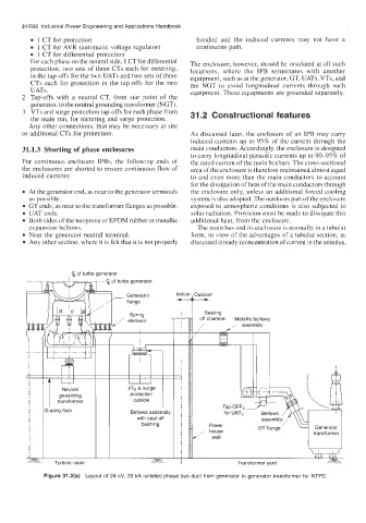
Figure 31.2(a) Layout of 24 kV, 20 kA isolated phase bus duct from generator to generator transformer for NTPC