
Page 986 - Industrial Power Engineering and Applications Handbook
P. 986
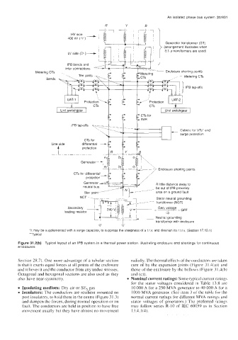
An isolated phase bus system  31/931
                               HV side  -              Y       B
                                              R


                              400 kV (y)
                                                                        Generator transformer (GT)
                                                                       (arrangement illustrates when
                                                                       3,l-9 transformers are used)
                              LV side (D )-

                              IPB bends and
                             inter connections
                Metering CTs                                            Enclosure shorting points
                                                                                Metering CTs
                     Bends
                                                                                IPB tap-offs


                           Unit switchgear                              Unit switchgear
                                                             CTs for
                                                             AVR
                                IPB tap-offs
                                                                              Cubicle for VTs'  and
                                                                              surge protection
                                    differential  -
                                     CTs for
                       Line side    protection
                                    GeneratorAd  '1 "L\
                       _.                              ~~~

                                 CTs for diffe  -         c2   !-    Enclosure shorting points
                                              a,  , , --b2 . . . . . . . . . . . . . . . . . . . . . . . . . . .


                                                                    A little distance away to
                                                                    be out of  IPB proximity
                                                                    area on a ground fault
                                                                    Stator neutral grounding
                                                                    transformer (NGT)
                                                                     Gen. voltage   GFF
                                                                        Li3
                                                        ~  -~       Neutral grounding
                                                                    transformer with enclosure
                                           -         -
              'It  may be supplemented with a surge capacitor, to suppress the steepness of a t.r.v. and diminish its r.r.r.v, (Section 17.10.1)
              "Typical
         Figure 31.2(b)  Typical layout of an IPB system in a thermal power station, illustrating enclosure end shortings for continuous
         enclosures


         Section 28.7). One more advantage of a tubular section   radially. The thermal effects of the conductors are taken
         is that it exerts equal forces at all points of the enclosure   care of  by the expansion joints  (Figure 31.4(a)) and
         and relieves it and the conductor from any undue stresses.   those of the enclosure by the bellows (Figure 3 1.4(b)
         Octagonal and hexagonal sections are also used as they   and (c)).
         also have  near-symmetry.                      0  Naminal current ratings: Some typical current ratings
                                                         for the  stator  voltages  considered  in  Table  13.8 are
           Insulating medium: Dry air or SF,  gas        10 000 A for a 250 MVA generator to 40 000 A  for a
         0  Insulators: The conductors are resilient mounted on   1000 MVA generator. (See item 3 of the table for the
           post insulators, to hold them in the centre (Figure 31.3)   normal current ratings for different MVA ratings and
           and dampen the forces, during normal operation or on   stator  voltages  of  generators.) The preferred ratings
           fault. The conductors are held in position to have free   may  follow series R-10 of  IEC  60059 as in  Section
           movement axially but they have almost no movement   13.4.1(4).