
Page 987 - Industrial Power Engineering and Applications Handbook
P. 987
31/932 Industrial Power Engineering and Applications Handbook
Emclosure
Figure 31.3 Arrangements of insulators to hold the busbars
Types of enclosures: These may be of two types, Le.
Non-continuous, and
Continuous.
31.2.1 Non-continuous or insulated enclosures
These were used until the early 1960s and have since
been discontinued in view of the inherent advantages of
a continuous enclosure. In non-continuous enclosures
the individual sections that are added together to obtain
the required length and configuration of the bus layout
are electrically insulated from each other. They are also
insulated from their mounting structures by rubber or
fibre-glass or similar insulating pads, as illustrated in
Figures 31.5(a) and (b). This is to prevent the longitudinal
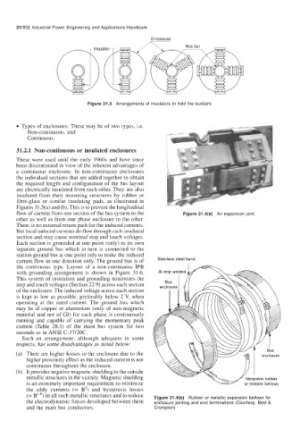
flow of current from one section of the bus system to the Figure 31.4(a) An expansion joint
other as well as from one phase enclosure to the other.
There is no external return path for the induced currents.
But local induced currents do flow through each insulated
section and may cause nominal step and touch voltages.
Each section is grounded at one point (only) to its own
separate ground bus which in turn is connected to the
station ground bus at one point only to make the induced
current flow in one direction only. The ground bus is of Stainless steel band
the continuous type. Layout of a non-continuous IPB
with grounding arrangement is shown in Figure 3 1.6. AI strip we
This system of insulation and grounding minimizes the
step and touch voltages (Section 22.9) across each section
of the enclosure. The induced voltage across each section
is kept as low as possible, preferably below 2 V, when
operating at the rated current. The ground bus which
may be of copper or aluminium (only of non-magnetic
material and not of GI) for each phase is continuously
running and capable of carrying the momentary peak
current (Table 28.1) of the main bus system for two
seconds as in ANSI C-37/20C.
Such an arrangement, although adequate in some
respects, has some disadvantages as noted below:
(a) There are higher losses in the enclosure due to the
higher proximity effect as the induced current is not
continuous throughout the enclosure.
(b) It provides negative magnetic shielding to the outside
metallic structures in the vicinity. Magnetic shielding
is an extremely important requirement to minimize
the eddy currents (= B2) and hysteresis losses
(= B1'6) in structures and to reduce Figure 31.4(b) Rubber or metallic expansion bellows for
the electrodynamic forces developed between them enclosure jointing and end terminations (Courtesy: Best &
and the main bus conductors. Crompton)