
Page 988 - Industrial Power Engineering and Applications Handbook
P. 988
An isolated phase bus system 31/933
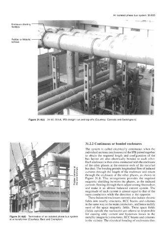
Enclosure shorting
flexibles
Rubber or Metallic
bellows
Figure 31.4(c) 24 kV, 20 kA, IPB straight run and tap-offs (Courtesy: Controls and Switchgears)
31.2.2 Continuous or bonded enclosures
The system is called electrically continuous when the
individual sections (enclosures) of the IPB joined together
to obtain the required length and configuration of the
bus layout are also electrically bonded to each other.
Each enclosure is then cross-connected with the enclosure
of the other phases at the extreme ends of the installed
c
ml? bus duct. The bonding permits longitudinal flow of induced
ZG
- currents through the length of the enclosure and return
-OE
2 through the enclosure of the other phases, as shown in
& 7 Figure 3 1.8. This arrangement provides the required
Dal magnetic shielding between the phases, as the induced
D
5 currents flowing through them adjust among themselves
and make it an almost balanced current system. The
magnitude of such current is almost equal to that of the
main conductors while the direction is the opposite.
These balanced enclosure currents also induce electric
fields into nearby structures, RCC beams and columns
in the same way as the main conductors, and hence nullify
most of the space magnetic fields. These space fields
(fields outside the enclosure) are otherwise responsible
for causing eddy current and hysteresis losses in the
Figure 31.4(d) Terrnlnatlon of an isolated phase bus system metallic (magnetic) structures, RCC beams and columns
at a transformer (Courtesy: Best and Crompton) in the vicinity. The electrical bonding of enclosures thus