
Page 990 - Industrial Power Engineering and Applications Handbook
P. 990
An isolated phase bus system 31/935
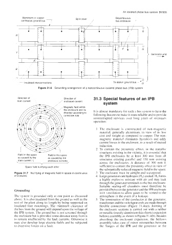
Aluminium or copper Split cover Discontinuous
continuous ground bus 7 7 bus enclosure -
-
i Generator end
To station ground bus - 'F
Insulated interconnections
~~~
Figure 31.6 Grounding arrangement of a noncontinuous isolated phase bus (IPB) system
Direction of Direction of 31.3 Special features of an IPB
main current / enclosure current
system
, Magnetic field within
the enclosure and its It is almost mandatory for such a bus system to have the
direction according to
corkscrew rule following features to make it more reliable and to provide
uninterrupted services over long years of strenuars
operation:
1 The enclosure is constructed of non-magnetic
material, generally aluminium, in view of its low
cost and weight as compared to copper. The non-
magnetic material eliminates hysteresis and eddy
current losses in the enclosure. as a result of mutual
induction.
2 To contain the proximity effect. in the metallic
structures existing in the vicinity, it is essential that
Field in the space Field in the space the IPB enclosures be at least 300 mm from all
as caused by the as caused by the structures existing parallel and 1 SO mm existing
main current I, enclosure currents
" across the enclosures. A distance of 300 rnm is
Space field nullifying each other sufficient to contain the proximity effect in view of
the substantially reduced magnetic field in the space.
Figure 31.7 Nullifying of magnetic field in space in continuous 3 The enclosure must be airtight and waterproof.
enclosures 4 Large generators are hydrogen (H,) cooled. H2 forms
a highly explosive mixture with air and may leak
through the generator terminals to the bus enclosure.
Suitable sealing-off chambers must therefore be
Grounding provided between the generator and the IPB enclosure
with ventilation to allow gases to be vented to the
Thc system is grounded only at one point as discussed atmosphere in the event of a leakage.
above. It is also insulated from the ground as well as the S The termination of the conductor at the generator,
rest of the plant along its length by being supported on transformer and the switchgear ends are made through
insulated foot mountings. The minimum clearance of flexible connections (Figure 3 1.4(a)). Jointing of
the bus from the ground will depend upon the voltage of the enclosure sections is carried out with a rubber
the IPB system. The ground bus is not screened through or metallic (mostly aluminium thin sheets) expansion
the enclosure but is provided some distance away from it bellows assembly, as shown in Figure 3 1.4(b). Besides
to remain unaffected by the fault currents. Otherwise it absorbing the enclosure expansion, the bellows
may also develop large electric fields and be subjected assembly takes care of minor mismatches between
to excessive forces on a fault. the flanges of the IPB and the generator or the