
Page 991 - Industrial Power Engineering and Applications Handbook
P. 991
31/936 Industrial Power Engineering and Applications Handbook
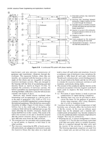
Unbonded portions may experience
excessive forces.
Shorting links (bonding) between
enclosures. It helps to balance the flow
of current through the enclosure.
Saturable reactors to limit the enclosure
currents and reduce the fault level and
losses caused by it.
Direction of current in the enclosures.
Enclosure induced currents can be up
to 0.90 to 0.95 I,.
Direction of current in the main
conductors.
Field produced by the enclosure
currents nuliifying the main field.
Residual field in the space = 1&5% of
the total field produced by C.
Figure 31.8 A continuous IPB system with phase reactors
transformers and also prevents transmission of tend to shear off such joints and structures. Even in
generator and transformer vibrations through- the a continuous type of enclosure it may not always be
enclosure. The expansion bellows, when they are possible to fully bond all such parts electrically.
metallic, are insulated with the housing as they are Should such a situation arise, current limiting reactors
made of thin sheets and are incapable of carrying may be provided at the bends and the tee-off joints
excessive enclosure currents. They are clamped to to contain the excessive enclosure currents at such
the housing with the help of an insulating pad and locations, particularly during faults.
metallic bands as shown in Figure 31.4(b). To 8 The exterior of the conductor and the interior of the
maintain the continuity of enclosure currents, the enclosure are painted with non-magnetic matt finish
bellow assemblies are superimposed with enclosure black paint to improve the heat transfer due to
shorting flefibles, sufficient to carry the full enclosure radiation.
currents (see Figure 3 1.4(c)). 9 (a) Provision of space heaters is made to prevent
However, they should remain insulated when condensation of vapour during a shutdown.
terminating with an equipment or a device such as (b) Shorting links may also be provided to short-
at the ends of generators, GTs, UATs or VTs. It is circuit the buses for the purpose of generator
essential to avoid IPB longitudinal currents through drying when required, after a long shutdown,
the terminal equipment. Now the bellows necessarily due to a fall in insulation level.
should be of rubber. Figure 31.4(d) shows a rubber IO Locations having low ambient temperature or high
bellows but in this small part of the bellows the humidity may adversely affect the insulation level
conductor field will not be nullified and occupy the of the bus system. In this case an ordinary space
space affecting the metallic structures, beams and heater may not be adequate and a separate anti-
equip-ment/devices in the vicinity. This needs to be condensation arrangement may become imperative
taken into account at site and it should be ensured to dry the condensate and to maintain a high dielectric
that the nearest structure, beam or equipment is at strength. This may be achieved by:
least 600 mm away from the IPB enclosure. Blowing hot air: A typical arrangement is shown
The terminal ends are provided with terminal palms in Figure 3 I .9. The bus duct enclosure is provided
or tap-off palms, as required, to bolt them to the with inlet and outlet valves at suitable locations.
other sections. Hot air is supplied through the inlet valve until
The structures supporting the IPB, at bends and tee- the interior of the enclosure is completely dry.
offs particularly, are adequately reinforced to sustain The blowing equipment comprises an axial flow
the excessive forces that may arise on a fault and fan, a heater unit, an inlet air filter unit, pressure