
Page 994 - Industrial Power Engineering and Applications Handbook
P. 994
An isolated phase bus system 311939
10 I 3.133 x IO-" x IO"
\ :
2n
09 I ... Spz,, = - 1 x50
= 1.26 cm or 12.6 mm
08 and 6pp8s 12.6 1/12.16
=
to/ = 14.01 mm
0 Since most of the current will tlow through SP, ;I thicker
$06
% conductor will only add to the bulk and cost of the tube
c penetration) without proportionately raising its current-carrying
5 0.5
k capacity. A greater thickness does not assist in heat
2 dissipation, as the heat is dissipated more quickly from
$04 lie = 0.368 the outside than the inside surface of a body.
c
_m
$03 31.4.2 Thickness of enclosure
For a near-total shielding of the field produced by the
02
main conductors (i.e. for I, - I, to be very low), it is
essential to have the thickness of the enclosure as near to
01 6, as possible. But this may prove to be a costly
proposition. In addition, a higher induced current in the
0 enclosure will also mean higher losses. This has been
0 1 6P 26P 36P established by computing the cost of the enclosure and
Depth from surface t +
capitalizing the cost of losses for minimum losses in the
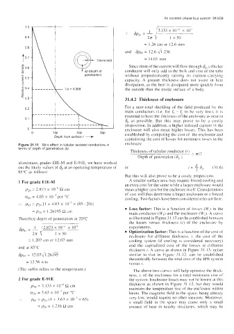
Figure 31.11 Skin effect in tubular isolated conductors in enclosure
terms of depth of penetration Sp
Thickness of tubular conductor (I j = rrI2
Depth of penetration )
aluminium, grades EIE-M and E-91E, we have worked t = IT 6, (31.6)
out the likely values of 6, at an operating temperature of or -
85°C a\ follows:
But this will also prove to be a costly proposition.
1 For grade EIE-M A smaller surface area may require forced cooling and
an extra cost for the same while a larger enclosure would
pzo = 2.873 x IO-" a cm mean a higher cost for the enclosure itself. Considerations
of cost will thus determine a larger enclosure or a forced
azo = 4.03 x IO-? per "C cooling. Two factors have been considered relevant here:
:. px4 = plo [I + 4.03 x IO-' x (85-ZO)]
Loss factor: This is a function of losses (W, in the
j
= p30 x 1.26195 R cm main conductor (W,) and the enclosure (W?). A curvc
Therefore depth ot penetration at 20°C as illustrated in Figure 3 1.12 can be established between
the losses versus thickness (t) of the enclosure by
experiments.
Optimization factor: This is a function of the cost of
enclosure for different thickness. 1, the cost of the
= 1.207 cm or 12.07 inm cooling system (if cooling is considered necessary)
and the capitalized cost of the losses at different
and at 85°C
thickness t. A curve as shown in Figure 3 1.13. rather
GpgT = 12.07.\/1.26195 similar to that in Figure 31.12, can be established
theoretically between the total cost of the IPB system
= 13.56 mm versus t.
(The suffix refers to the temperature.) The above two curves will help optimize the thick-
ness, t, of the enclosure for a total rninirriurri ~osl oP
2 For grade E-91E the system. Enclosure losses may not be lowest at this
pZn = 3. I 33 x I OF cm thickness as shown in Figure 31.12, but they would
maintain the temperature rise of the enclosure within
a2,] = 3.63 x lo-' per "C limits. The magnetic field in the space. being already
:. ps5 = pzo ( 1 + 3.63 x IO-' x 65) very low, would require no other measure. Moreover.
a small field in the space may causc only a small
= p20x I 236 !2 cm amount of heat in nearby structures, which may be