
Page 998 - Industrial Power Engineering and Applications Handbook
P. 998
An isolated phase bus system 31/943
the generator transformer will be subject to a higher fault
level commensurate with the fault level of the power grid
limited upto the fault level of GT (Section 13.4.1.5 and
Figure 13.1 I ). Similarly. the tap-offs connecting the UATs
will be subject to a cumulative fault level. one of the
generator and the other of the power grid (limited up to
GT). Generally, therefore such large ratings ofbus systems
are subject to a high fault level. (For a few large ratings
!
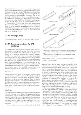
of bus systems these lehels are shown in Table 13.8). Octagonal section ,A3
For ratings of 25000 A and above it is possible that
the fault level of the system may exceed the rupturing
capacity of the available interrupting devices. To reduce
the fault level in such cases, current limiting series reactors
can be provided with the bus system, as noted above and
illustrated in Figure 3 I .8.
Hexagonal section
31 .I 0 Voltage drop
As di~ussed earlier. this has no relevance in HT systems.
31.11 Forming sections for IPB
systems
It is not possible to extrude large sections in full circular,
hexagonal or octagonal shapes. These are norinally * Slits are left (- 50 mm wide) to facilitate heat dissipation from the
inside surface of the conductors [enclosures are totally closed]
produced in smaller extruded sections as illustrated in Note
Figure 3 I. 15. Circular sections may, however, also be Number of sections would depend upon the dimensions of the
rolled from sheets in two halves to obtain the desired conductor or the enclosure
size. Moderate sizes of circular sections are also available
in extruded form. For hexagonal and octagonal shapes. Figure 31.15 Forming a conductor or enclosure from the
the thickness and lengths of such sections will depend available extruded sections
upon the practices adopted by the manufxturer of the
extruded sections. The desired size of conductor and designs, there are no ready reckoners available from
enclosure can then be shop fabricated out of these sections, aluminium manufacturers of extruded sections to quickly
choosing the nearest next available size. to form them determine their current ratings. This may be established
into the required sire of conductor and enclosure. only by conducting shop tests. It is not recommended to
assign the rating on the basis of per unit area in view of
Enclosures a number of factors that may influence the rating. such
Sinall margins are added in enclosures for inspection as the surface area, the thickness of the enclosure or the
and maintenance windows and tap-offs, which may affect conductor sections and ambient conditions. The design
their current ratings. These sections are welded circum- of a bus section is a matter of experience of the design
ferentially to give them the required shape (circular, engineer. As a rough guide, however. to establis,h the
hexagonal or octagonal). They are welded longitudinally basic parameters, a rating around 350 to 300 Ah- may
to shape them into the required length and configuration. be considered which will also take
Extreme care must be taken when making such joints, to deratings. (Refer to the sample calculations in Example
make them airtight and to ensure maximum continuity 3 1. I .) The normal practice is to use a computer. which
of current. can provide a number of alternative designs.
The cross-sections of the conductor and the enclosure
Conductor are then checked for their adequacy to dis-ipate the heat
generated. The cross-section is then adjusted suitably by
The conductor may not have any inspcction or maintenance permutations and combinations to arrive at the most
windows. but may be provided with surface openings, as appropriate size. keeping in mind the available extruded
illustrated in Figure 3 1.15 to dissipate its interior heat sections, accounting for all such factors that may affect
into the enclosure for onward dissipation by the enclosure’s the rating or the fault level of the enclosure and the
wrface to the atmosphere. This facility. however, may conductor. such as tap-offs. which are subjected to a
not be available in smaller circular conductors if they are cuinulative fault level, openings in the conductor for heat
extruded as one piece (which is possible in smaller dissipation or the enclosure for inspection windows that
sections). can influence their ratings. A calculation in Example
Since the alumini~im sections are formed to individual 3 I. I will clarify the procedure to establish the sire of the