
Page 862 - Mechanical Engineers' Handbook (Volume 2)
P. 862
8 Sensors 853
converter can produce 16 different output states. Issues to consider closely when selecting a
D/A converter include the resolution and the amount of current that can be supplied.
8 SENSORS
8.1 Position Sensors
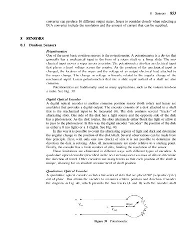
Potentiometers
One of the most basic position sensors is the potentiometer. A potentiometer is a device that
generally has a mechanical input in the form of a rotary shaft or a linear slide. The me-
chanical input moves a wiper across a resistor. The potentiometer also has an electrical input
that places a fixed voltage across the resistor. As the position of the mechanical input is
changed, the location of the wiper and the voltage of an output electrical lead attached to
the wiper change. The change in voltage is linearly related to the angular change of the
mechanical input. Linear potentiometers that use a slide input instead of a shaft are also
common.
Potentiometers are traditionally used in many applications, such as the volume knob on
a radio. See Fig. 39.
Digital Optical Encoder
A digital optical encoder is another common position sensor (both rotary and linear are
available) that provides a digital output. The encoder consists of a disk attached to a shaft
that is the mechanical input to be measured ( ). The disk contains several ‘‘tracks’’ of
alternating slots. One side of the disk has a light source and the opposite side of the disk
has a photosensor. As the disk rotates, the slots alternately either block the light or allow it
to pass to the photosensor. In this way the digital encoder ‘‘encodes’’ the position of the disk
as either a 0 (no light) or a 1 (light). See Fig. 40.
In this way it is possible to count the alternating regions of light and dark and determine
the angular change in the position of the disk/shaft. Several observations can be made from
this principle. First, with only one row (track) of slits it is not possible to determine the
direction the disk is rotating. Also, all measurements are made relative to a starting point.
Finally, the encoder has a finite number of slits, limiting the resolution of the sensor.
These limitations are eliminated in different ways with different types of encoders. A
quadrature optical encoder (described in the next section) uses two rows of slits to determine
the direction of travel. Other encoders use many tracks so that each position of the shaft is
unique, allowing for an absolute measurement of shaft position.
Quadrature Optical Encoder
A quadrature optical encoder includes two rows of slits that are placed 90 (a quarter cycle)
out of phase. This allows the encoder to measures relative position and direction. Consider
the diagram in Fig. 41, which presents the two tracks (A and B) with the encoder shaft
+
Wiper
V in
+
V out
–
–
Figure 39 Potentiometer.