
Page 863 - Mechanical Engineers' Handbook (Volume 2)
P. 863
854 Mechatronics
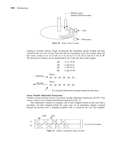
Multiple tracks,
multiple LED/sensor pairs
LED
Photosensor
Figure 40 Rotary optical encoder.
rotating at constant velocity. Figure 41 presents the alternating regions of light and dark
created by the two rows of slits. Since the slits are one-quarter cycle out of phase, there are
four states created: (1) A on, B off; (2) A on, B on; (3) A off, B on; and (4) A off, B off.
The direction of rotation can be determined by the order that these states appear:
AB A on, B off
AB A and B on
AB A off, B on
AB A and B off
Output
Direction
A B AB A B A B A B AB ...
Output
Direction
A B A B A B AB A B A B
You can get the direction by noting the change that takes place.
Linear Variable Differential Transformer
Another common position sensor is the linear variable differential transformer (LVDT). This
sensor is based on an electrical transformer depicted in Fig. 42.
The transformer consists of a primary coil of wire wrapped around an iron core with a
secondary coil also wrapped around the same core. As an alternating current is passed
through the primary core, a changing magnetic field is created by the coil. The magnetic
Dark light
A
1/4 cycle out of phase
B
Figure 41 Output of quadrature optical encoder.