
Page 865 - Mechanical Engineers' Handbook (Volume 2)
P. 865
856 Mechatronics
Transverse axis
Measuring axis (axial)
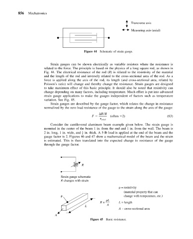
Figure 44 Schematic of strain gauge.
Strain gauges can be shown electrically as variable resistors where the resistance is
related to the force. The principle is based on the physics of a long square rod, as shown in
Fig. 44. The electrical resistance of the rod (R) is related to the resistivity of the material
and the length of the rod and inversely related to the cross-sectional area of the rod. As a
force is applied along the axis of the rod, its length (and cross-sectional area, related by
Poisson’s ratio) will change and thereby change the resistance. Strain gauges are designed
to take maximum effect of this basic principle. It should also be noted that resistivity can
change depending on many factors, including temperature. Much effort is put into advanced
strain gauge applications to make the gauges independent of factors such as temperature
variation. See Fig. 45.
Strain gauges are described by the gauge factor, which relates the change in resistance
normalized by the zero load resistance of the gauge to the strain along the axis of the gauge:
R/R
F (often 2) (63)
axial
Consider the cantilevered aluminum beam example given below. The strain gauge is
mounted in the center of the beam 1 in. from the end and 1 in. from the wall. The beam is
2 in. long, 1 in. wide, and – 1 in. thick. A 5-lb load is applied at the end of the beam and the
8
gauge factor is 2. Figures 46 and 47 show a mathematical model of the beam and the strain
is estimated. This is then translated into the expected change in resistance of the gauge
through the gauge factor.
R
Strain gauge schematic
R changes with strain
= resistivity
(material property that can
change with temperature, etc.)
L
R = L = length
L A
A – cross-sectional area
A
Figure 45 Basic resistance.