
Page 868 - Mechanical Engineers' Handbook (Volume 2)
P. 868
9 Electromechanical Modeling Example 859
V V ex (R ) V ex
4
AB
R R 3 3 R R 4 R 0 (84)
1
2
and
V V
V AB ex R 2 R 1 ex R 1 R 2 (85)
R R 3 R R 4 R R 4 R R 3
1
1
2
2
We now deform the strain gauge (R becomes R R ):
1
1
1
R R R
V AB 1 1 2
(86)
(R R ) R R R
V ex 1 1 4 2 3
Equation (86) relates V AB to R where R is related to strain.
Shuffle (86):
R 4 V AB R 2
R 1 V ex R R 3
2
1 V AB R 2
R R 1 (87)
1
1
V ex R R 3
2
Use (87) and
R/R
F (88)
axial
This analysis [(63)–(88)] gives an example of how to design a system with strain sensors.
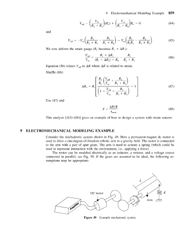
9 ELECTROMECHANICAL MODELING EXAMPLE
Consider the mechatronic system shown in Fig. 49. Here a permanent-magnet dc motor is
used to drive a one-degree-of-freedom robotic arm in a gravity field. The motor is connected
to the arm with a pair of spur gears. The arm is used to actuate a spring (which could be
used to represent interaction with the environment, i.e., applying a force).
The motor can be modeled electrically as an inductor, a resistor, and a voltage source
connected in parallel; see Fig. 50. If the gears are assumed to be ideal, the following as-
sumptions may be appropriate:
L
DC motor K
Arm
Figure 49 Example mechatronic system.