
Page 869 - Mechanical Engineers' Handbook (Volume 2)
P. 869
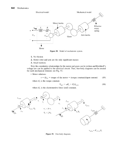
860   Mechatronics
                                  Electrical model                     Mechanical model


                                                 Motor inertia
                                                                                       Effective
                                i in          L           R                            rotary
                             +                                                         spring
                                                +
                                                                           Arm inertia
                                  V in
                                            V emf              Gears

                                                    –
                            –
                                      Motor
                                               Figure 50 Model of mechatronic system.

                             1. No friction
                             2. Motor rotor and arm are the only significant masses
                             3. Small motions
                             Now the constitutive relationships for the motor and gears can be written and Kirchhoff’s
                          voltage law can be applied to the electrical circuit. Then, free-body diagrams can be created
                          for each mechanical element; see Fig. 51:
                             • Motor relations:
                                          Ki   torque of the motor   (torque constant)(input current)  (89)
                                           t in
                               where K is the torque constant.
                                     t
                                                                     ˙
                                                       V emf     K   K                        (90)
                                                                    e motor
                                                                e
                               where K is the electromotive force (emf) constant.
                                     e

                 I  motor
                                    1
                      I  arm
                                        1
            2

 spring
                                ⋅⋅
                            I   motor    m
 2  = N
 1
 2
                                                                        ⋅⋅

 in               ⋅    ⋅                        I a   a
 spring
                                           a  =  1    m
                m                            N

                                                           a


 spring  =  K  effective   a
                                           Figure 51 Free-body diagrams.