
Page 575 - Polymer-based Nanocomposites for Energy and Environmental Applications
P. 575
528 Polymer-based Nanocomposites for Energy and Environmental Applications
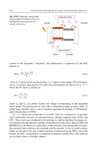
Fig. 19.10 Schematic energy band Conduction band
representation of a bilayer solar cell
showing the basic processes of 2 3 4 5
Anode Cathode
energy conversion.
1
5 4
Valence band
Donor Acceptor
carriers at the electrodes. Concretely, the performance is expressed by the PCE
defined as
J SC V OC FF
PCE ¼ (19.6)
P in
where J SC is short-circuit current density, V OC is open-circuit voltage, FF is fill factor,
and P in is incident input power. The solar cell characteristics are shown in Fig. 19.11
where the fill factor is defined as
J M V M
FF ¼ (19.7)
J SC V OC
where J M and V M are current density and voltage corresponding to the maximum
power point. The performance of solar cells is determined under air mass (AM) 1.5
global solar standard, that is, with an incident spectrum of intensity of 100 mA/cm 2
and at temperature of 300 K.
Fig. 19.12 shows the architecture of an OPV. They are composed of an absorber
layer sandwiched between two transport layers: electron transport layer (ETL) and
HTL. These layers are introduced to the structure in order to facilitate the charge car-
rier transport into the absorber and their extraction out of this layer. Their LUMO and
HOMO levels are chosen to match those of the absorber and consequently to reduce
the potential barrier between the electrode and the absorber. In the inverted configu-
ration, on the top of the cell, a metal electrode is deposited on the HTL, and at the
bottom, the ETL is deposited on a transparent electrode (usually ITO). The substrate
can be rigid (glass) or flexible (plastic).