
Page 476 - Rock Mechanics For Underground Mining
P. 476
LONGWALL AND CAVING MINING METHODS
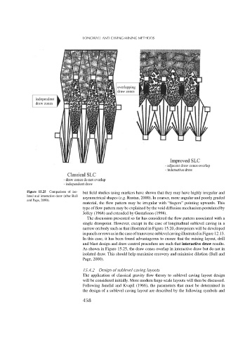
Figure 15.25 Comparison of iso- but field studies using markers have shown that they may have highly irregular and
lated and interactive draw (after Bull asymmetrical shapes (e.g. Rustan, 2000). In coarser, more angular and poorly graded
and Page, 2000).
material, the flow pattern may be irregular with “fingers” pointing upwards. This
type of flow pattern may be explained by the void diffusion mechanism postulated by
Jolley (1968) and extended by Gustafsson (1998).
The discussion presented so far has considered the flow pattern associated with a
single drawpoint. However, except in the case of longitudinal sublevel caving in a
narrow orebody such as that illustrated in Figure 15.20, drawpoints will be developed
in panels or rows as in the case of transverse sublevel caving illustrated in Figure 12.13.
In this case, it has been found advantageous to ensure that the mining layout, drill
and blast design and draw control procedure are such that interactive draw results.
As shown in Figure 15.25, the draw cones overlap in interactive draw but do not in
isolated draw. This should help maximise recovery and minimise dilution (Bull and
Page, 2000).
15.4.2 Design of sublevel caving layouts
The application of classical gravity flow theory to sublevel caving layout design
will be considered initially. More modern large-scale layouts will then be discussed.
Following Janelid and Kvapil (1966), the parameters that must be determined in
the design of a sublevel caving layout are described by the following symbols and
458