Page 477 - Rock Mechanics For Underground Mining
P. 477
SUBLEVEL CAVING

                                        nomenclature:

                                            A = width of the slice (Figure 15.26)
                                            H = height of the extraction drift (Figure 15.26)
                                            B = width of the extraction drift (Figure 15.26)
                                            P = width of the pillars between extraction drifts (Figure 15.26)
                                            V = ring burden (Figure 15.23a)
                                            K = factor dependent upon the particle size distribution in the broken ore
                                        a N , b N = major and minor semi-axes of the ellipsoid of motion (Figure 15.23b)
                                             c = width of the extraction point (Figure 15.27)
                                            r = semi-width of the limit ellipsoid at the height h N (Figure 15.24)
                                            x = digging depth of the loader (Figure 15.28)
                                              = gradient of the slice (Figure 15.23a)
                                              = angle of repose of the ore in the draw point (Figure 15.28)
                                             ε = eccentricity of the ellipsoid of motion.

                                          The interrelations between these design parameters are complex, so that universally
                                        applicable design equations are difficult to establish. However, the theory of gravity
                                        flow outlined in the previous section does lead to some relations that have been used
                                        in layout design.
                                          Consideration of the progress of ore and waste flows indicates that a staggered
                                        arrangement of extraction drifts such as that shown in Figure 15.26 is generally
                                        preferable to one in which the drifts on successive sublevels are aligned vertically.
                                        With this arrangement, h N   2S as shown in Figure 15.26. The optimum burden for
                                        any slice height may be related to the minor semi-axis of the ellipsoid of flow as
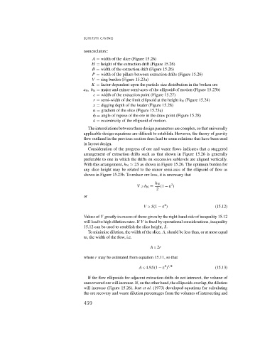
                                        shown in Figure 15.23b. To reduce ore loss, it is necessary that

                                                                         h N     2
                                                                 V   b N =  (1 − ε )
                                                                          2
                                        or

                                                                              2
                                                                    V   S(1 − ε )                    (15.12)
                                        Values of V greatly in excess of those given by the right-hand side of inequality 15.12
                                        will lead to high dilution rates. If V is fixed by operational considerations, inequality
                                        15.12 can be used to establish the slice height, S.
                                          To minimise dilution, the width of the slice, A, should be less than, or at most equal
                                        to, the width of the flow, i.e.

                                                                       A   2r

                                        where r may be estimated from equation 15.11, so that

                                                                              2 1/2
                                                                  A   4.9S(1 − ε )                   (15.13)
                                          If the flow ellipsoids for adjacent extraction drifts do not intersect, the volume of
                                        unrecovered ore will increase. If, on the other hand, the ellipsoids overlap, the dilution
                                        will increase (Figure 15.26). Just et al. (1973) developed equations for calculating
                                        the ore recovery and waste dilution percentages from the volumes of intersecting and
                                        459

