
Page 480 - Rock Mechanics For Underground Mining
P. 480
LONGWALL AND CAVING MINING METHODS
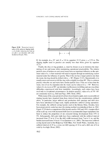
Figure 15.28 Theoretical determi-
nation of the optimum digging depth,
x, of a loader extracting ore from an
ore pile in an extraction drift (after
Janelid and Kvapil, 1966).
◦
If, for example, = 35 and H = 3.0 m, equation 15.15 gives x = 2.72 m. The
digging depths used in practice are usually less than those given by equation
15.15.
Finally, the slice or ring gradient, , must be chosen so as to minimise the inter-
mixing of ore and waste while maintaining operational practicability. The relative
particle sizes of broken ore and caved waste have an important influence on the opti-
mum value of . A finer material will tend to migrate through an underlying coarser
material under the influence of gravity. Thus if the ore has a larger particle size than
◦
the waste, the ring should be drilled with < 90 (Figure 15.23). Operationally, it is
◦
usually most convenient to drill the ring with slightly less than 90 . This is common
practice when the ore and waste have similar particle sizes. If the ore is finer than the
waste, loss of ore by migration into the waste can be reduced if > 90 . However,
◦
◦
values of in excess of 90 can introduce inefficiencies in drilling and can exacerbate
difficulties experienced with brow instability. Accordingly, such values have been
used only in exceptional circumstances. In modern practice, values of of 70 –90 ◦
◦
are commonly used (e.g. Bull and Page, 2000, Trout, 2002).
Whilemanyoftheconceptsinvolvedhavebeenfoundtoapply,morerecentsublevel
stoping layouts have departed from those derived from the considerations outlined
above. In particular, larger sublevel and production drift spacings and drift sizes
have been introduced in large-scale, highly productive sublevel caving operations.
For example, the sublevel caving layouts used at the Kiruna Mine, Sweden, have
been progressively scaled up since the mining method was introduced there in 1962.
Figure 15.29 shows a comparison of the layouts used in 1983 and 1993. A major effect
of the scale-up, even with increased drift sizes to accommodate larger equipment, has
been to reduce the proportion of ore extracted during development from 15% to
5%. Subsequently, full-scale trials have been conducted with the sublevel interval
increased from 27 m to 32 m, the drift width increased from7mto11m,and the
burden increased from 3.0 m to 3.5 m (Quintero et al., 2001). The transverse sublevel
caving layout used at the Ridgeway Gold Mine, New South Wales, Australia, has a
sublevel interval of 25 m, a cross-cut drift spacing of 14 m and a drift size of 6 m
wide by 4 m high (Trout, 2002).
462